Pololu Blog »
Pololu Blog (Page 15)
Welcome to the Pololu Blog, where we provide updates about what we and our customers are doing and thinking about. This blog used to be Pololu president Jan Malášek’s Engage Your Brain blog; you can view just those posts here.
Popular tags: community projects new products raspberry pi arduino more…
Bigger 3D printed buttons for the Zumo 32U4
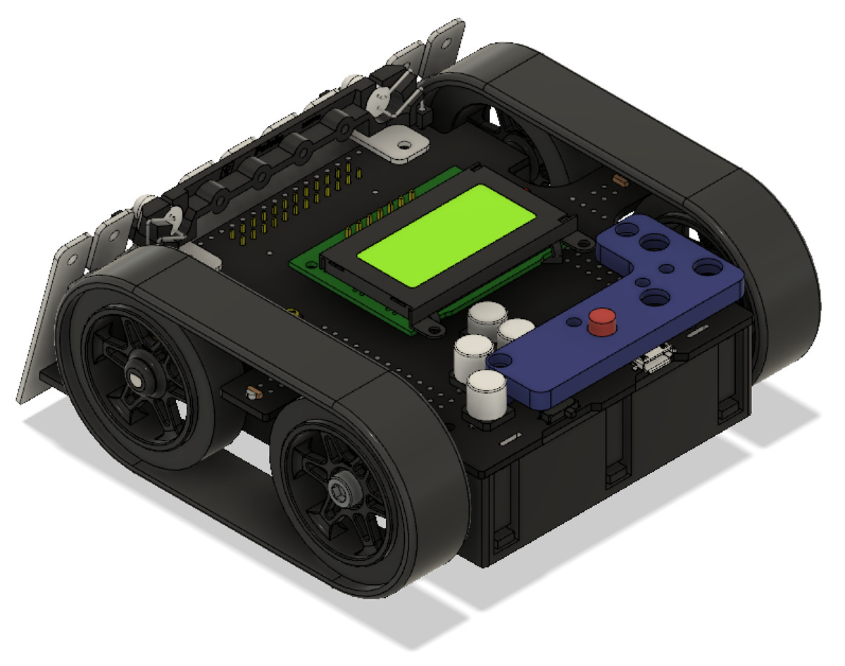 |
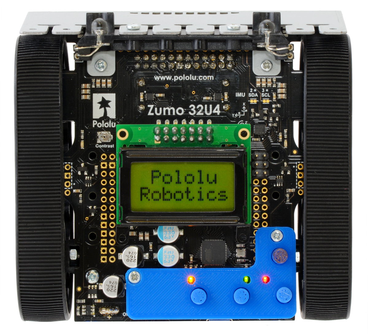
Mount Holyoke College professor Peter Klemperer designed a custom add-on for the Zumo 32U4 to give easier access to the user pushbuttons. Peter made the bigger buttons as a response to some of the students in his classes finding it difficult to use the small onboard pushbuttons.
The design even has small cutouts so you can still see the indicator LEDs. To add the adapter plate to the Zumo chassis, you can use two #2 screws and nuts (7/16 inch length screws worked great for me). The easy-to-print STL files along with the Fusion 360 files are available on Peter’s GitHub repository for the project, and you can find more information on Peter’s blog post on his website.
If you print your own bigger buttons for your Zumo 32U4 be sure to let him (and us!) know; we would love to see some pictures! Here’s a shot of the one I printed out for my personal Zumo 32U4:
 |
Related products


Firmware update for Tic Stepper Motor Controllers, with new features including limit switches and homing
 |
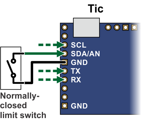 |
Connecting a limit switch to the Tic (SCL, SDA, TX, and RX pins). |
|---|
To go along with last week’s release of the Tic T249, we have also released a new version of the Tic firmware (version 1.06) for all Tic stepper motor controllers that adds several new features.
By popular demand, this new firmware version adds support for limit switches: any of the Tic control pins (SCL, SDA, TX, RX, or RC) can be configured as a digital input for a forward or reverse limit switch. When the limit switch is active, the Tic abruptly shuts down any movement in the specified direction, but allows the stepper motor to move in the other direction. You can use limit switches to help prevent your system from leaving its desired range of motion.
If you configure a limit switch, you can use the Tic’s new homing procedure. The new “Go home” command, which is available over serial, I²C, and USB, starts the homing procedure. The Tic will move in the direction specified by the command until it hits a limit switch for that direction. Then it will change directions, move until the limit switch deactivates, and set its current position to 0. The stepping speeds used by the Tic during the homing procedure are configurable.
You can also use the homing feature automatically, without sending a command. If automatic homing is enabled, the Tic performs the homing procedure whenever it is being commanded to go to a specific position but it is uncertain of its current position (e.g. immediately after motor power is applied). This feature can be handy if you are controlling the position of your stepper motor using an RC, analog, or quadrature encoder signal.
We have added a new section to the Tic user’s guide with detailed instructions for setting up limit switches and homing.
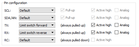 |
Example pin configuration for a Tic with limit switches. |
|---|
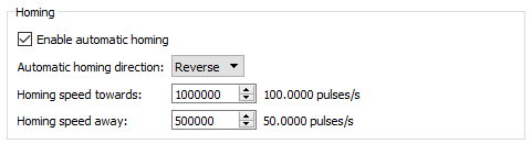 |
New homing settings added in Tic firmware version 1.06. |
|---|
The new firmware version also adds several features to the Tic’s TTL serial interface that make it more usable in systems with large numbers of Tics and in half-duplex serial busses. Specifically, it adds support for an alternative device number so any Tic can optionally be addressed by two different device numbers, and it adds an option to enable 14-bit device numbers so you can have more than 128 devices on a serial bus. The new firmware version also has an option to encode its serial responses using only bytes between 0 and 127, which can be useful in setups where the serial response from one Tic will be seen by other Tic devices, and you don’t want it to be misinterpreted as a command. We also implemented several changes to make the Tic less susceptible to noise on the serial lines, and you can now enable CRC bytes for serial responses sent by the Tic so that you can confirm the data you received matches what the Tic sent.
The Tic T249 was released with the latest firmware, so it has all of these new features, and we will be upgrading our existing Tics to this firmware version as we manufacture more. To gain access to these new features on your existing Tic controllers, you can download the latest configuration software and upgrade your device’s firmware to version 1.06. For more information, see the firmware upgrade instructions in the Tic user’s guide.
Related products


Macro photography using Tic stepper motor controllers
|
|
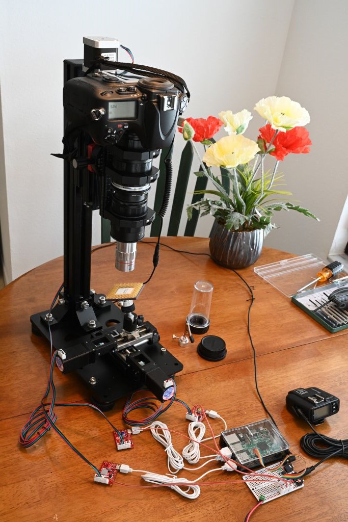
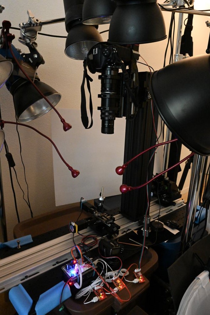
Forum member Mike is using our Tic stepper motor controllers in his automated stack & stitch image acquisition systems, which he has been using to get extremely high resolution images of various integrated circuits. Each system uses linear rails and stepper motors to properly align the camera/lens and the object to be photographed. Two stepper motors position the subject and a third adjusts how close the camera is to the subject. A Tic T500 controls each stepper motor and each Tic connects to a USB port on a Raspberry Pi 3B or Raspberry Pi 3B+, which acts as the main computer. Afterward, Mike stacks the images with Zerene Stacker and stitches them together with Photoshop. Some of his image sessions capture as many as 6000 individual images that are used to produce a single 300 megapixel image!
 |
Zooming in on a stack & stitch test image. |
|---|
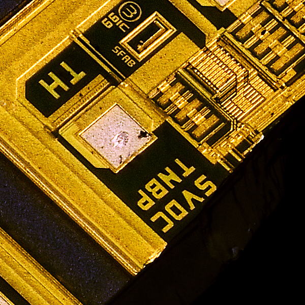 |
A close-up view of a stack & stitch test image. |
|---|
You can find more information about Mike’s stack & stitch image acquisition systems (like what specific mechanical hardware he is using) in this forum post. Also, to see and/or download a set of high resolution pictures taken with those setups, follow this link.

New product: Tic T249 USB Multi-Interface Stepper Motor Controller

I am excited to announce the release of the Tic T249 USB Multi-Interface Stepper Motor Controller, the fourth model in our line of Tic Stepper Motor Controllers. The Tic T249, which is based on the TB67S249FTG IC from Toshiba, features a broad 10 V to 47 V operating range and can deliver up to approximately 1.8 A per phase without a heat sink or forced air flow, making it our highest-power Tic yet. In addition to the array of high-level features offered by the other members of our Tic family, the Tic T249 offers access to several innovative features of the TB67S249FTG driver. Continued…
Rover team from IIT Madras places first in Indian Rover Challenge
 |
Congratulations to Team Anveshak from IIT Madras, who took first place at the 2019 Indian Rover Challenge! The IRC is a robotics and space exploration-based competition for college students. Participating teams design and build a Martian rover prototype and use that rover to compete in various tasks like obtaining soil samples, operating electrical racks, and picking up and delivering objects.
|
|
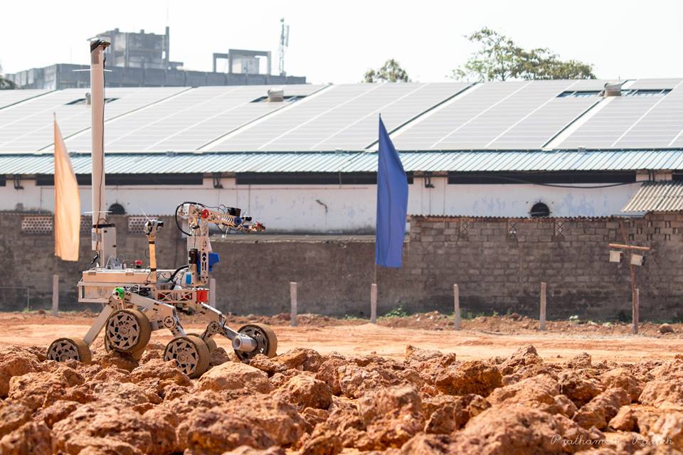
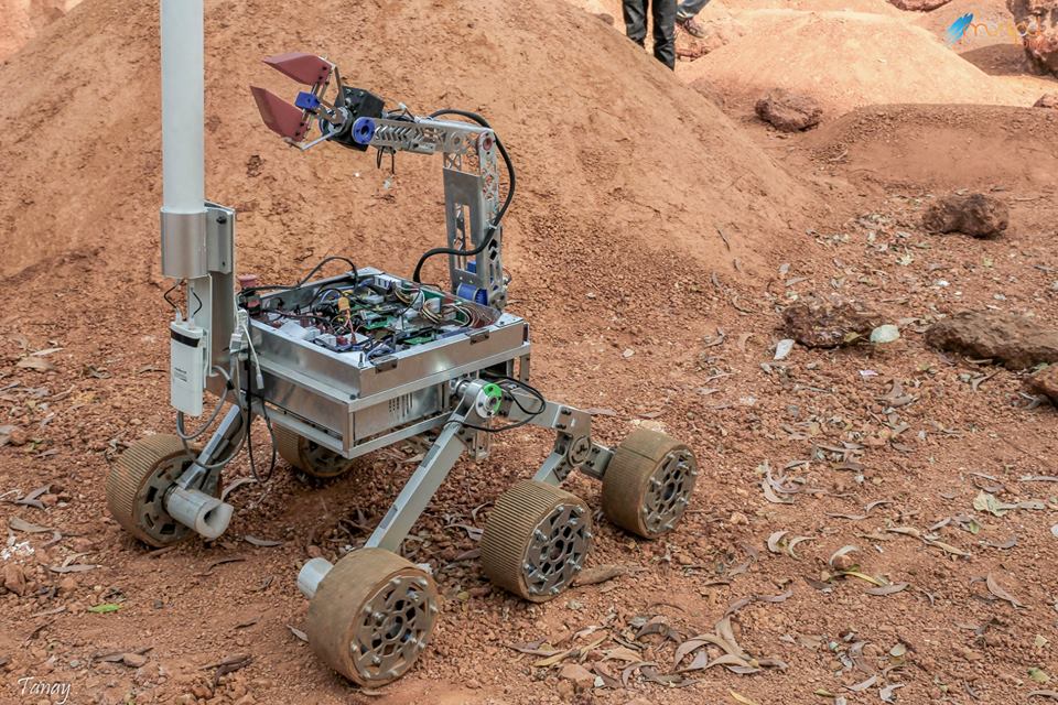
Team Anveshak’s winning rover, Caesar, uses 10 different Pololu products! We are especially excited to hear that their rover prominently features our newer G2 High-Power Motor Driver 24v13 and TB9051FTG motor drivers, using 9 of each of those boards.
We love seeing all the awesome things like this that people are doing with our products! For a more complete list of the Pololu parts used in Caesar, check out the related products listed below. If you want to learn more about the team, check out their website.
8 March 2019 Update: See a video of Caesar in action here.
Related products


TI Robotics System Learning Kit (TI-RSLK) in EDN’s hot 100 products of 2018
|
|


EDN recently released their hot 100 products of 2018, and we are excited to share that the TI Robotics System Learning Kit (TI-RSLK), which is based on our Romi platform, is included in the list. For those not familar with the TI-RSLK, it is a complete robotics kit and curriculum aimed at university students. Twenty modules with lecture notes, lab activities, and over a hundred videos are all publicly available.
The kit was included in the Tools & Development section of the list, and you can read EDN’s review of the kit from earlier in the year here. Kits can be purchased from Element14.
New Tic T500 revision to address problem with missed steps
One of the fun things you learn as an engineer is that physically laying out a circuit requires a lot more than simply confirming it matches the schematic. In practice, there are many more things to think about, and if you’ve seen datasheets with layout guidelines or recommendations, you’re probably aware of some of them. (Thermal considerations, adequate decoupling, minimizing parasitic inductance and capacitance…) What’s more, these considerations are often in conflict (e.g. is it better to have the decoupling capacitor closer to the IC or to have a wider trace for that high-current path?), and trouble can arise if you don’t correctly assess their relative importance. That is what happened to us with our Tic T500 stepper motor controller, where the location of a specific decoupling capacitor ended up being far more significant than we had anticipated. Continued…
New product: STSPIN220 Low-Voltage Stepper Motor Driver Carrier with 1/256 microstepping
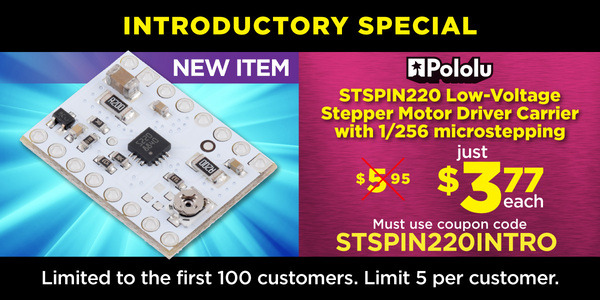
I am happy to announce our first new product of 2019, a carrier board for the STSPIN220 stepper motor driver, which operates all the way down to 1.8 V, making it our lowest-voltage stepper motor driver. And like its higher-voltage sibling, the STSPIN820 that we released a few months ago, it offers microstepping down to 1/256 steps. This new carrier board has the same 16-pin, 0.6″ × 0.8″ form factor as our other popular stepper motor drivers, and as with our STSPIN820 carrier, it inverts the enable input so that it has the more familiar functionality of those drivers (but be careful not to pop these into a 12 V or 24 V socket!).
By the way, keep in mind that you do not necessarily need a low-voltage stepper motor driver just because your stepper motor has a low rated voltage. The voltage rating is just the voltage at which your stepper motor will draw its rated current, and it’s really the current rating that you need to be careful about if you want to avoid damaging your stepper motor. All of our stepper motor drivers let you limit the maximum current, so as long as you set the limit below the rated current, you will be within spec for your motor, even if the voltage exceeds the rated voltage. In general, using a high supply voltage along with active current limiting allows for better performance, so the main reason for using a low-voltage stepper motor driver like the STSPIN220 is if your supply voltage is constrained to some low value by some other aspect of your system.
This new release brings our selection of stepper motor drivers in this compact form factor to eleven:
 A4988 (original) |
 A4988, Black Ed. |
 DRV8825 |
 DRV8834 |
 DRV8880 |
 MP6500, Pot. CC |
 MP6500, Digital CC |
 TB67S279FTG |
 TB67S249FTG |
 STSPIN820 |
 STSPIN220 |
|
|---|---|---|---|---|---|---|---|---|---|---|---|
| Driver chip: | A4988 | DRV8825 | DRV8834 | DRV8880 | MP6500 | TB67S279FTG | TB67S249FTG | STSPIN820 | STSPIN220 | ||
| Min operating voltage: | 8 V | 8.2 V | 2.5 V | 6.5 V | 4.5 V | 10 V | 10 V | 7 V | 1.8 V | ||
| Max operating voltage: | 35 V | 45 V | 10.8 V | 45 V | 35 V | 47 V | 47 V | 45 V | 10 V | ||
| Max continuous current per phase:(1) | 1 A | 1.2 A | 1.5 A | 1.5 A | 1 A | 1.5 A | 1.1 A | 1.6 A | 0.9 A | 1.1 A | |
| Peak current per phase:(2) | 2 A | 2.2 A | 2 A | 1.6 A | 2.5 A | 2 A | 2 A | 4.5 A | 1.5 A | 1.3 A | |
| Microstepping down to: | 1/16 | 1/32 | 1/32 | 1/16 | 1/8 | 1/32 | 1/32 | 1/256 | 1/256 | ||
| Board layer count: | 2 | 4 | 4 | 4 | 4 | 4 | 4 | 4 | 4 | 4 | |
| Special features: | high current | low-voltage operation, high current |
AutoTune, digital current reduction |
high current | digital current control, high current |
Auto Gain Control, ADMD, high max voltage |
Auto Gain Control, ADMD, high max voltage, high current |
128 and 256 microsteps, high max voltage |
64, 128, and 256 microsteps, low-voltage operation |
||
| 1-piece price: | $6.85 | $7.42 | $14.78 | $9.53 | $8.95 | $8.65 | $8.65 | $13.13 | $15.75 | $17.43 | $9.53 |
| 1 On Pololu carrier board, at room temperature, and without additional cooling. 2 Maximum theoretical current based on components on the board (additional cooling required). |
|||||||||||
Last year, we began offering introductory specials to celebrate each newly released product, and we are continuing with that this year: the first 100 customers that use coupon code STSPIN220INTRO can get up to five units at just $3.77 each.
Related products


Balboa controlled via cell phone over Bluetooth
Drew Wilkerson added a Robotis BT-410 Bluetooth-to-serial board to his Balboa Robot, which allows him to control that Balboa from a cell phone. You can watch the video above to see the Balboa being driven around as it balances. More information about this project, including the code running on Drew’s Balboa, can be found in his post on our forum.
Related products

Video: Easy Acrylic Unmasking
We do a lot of laser cutting here at Pololu as part of our custom laser-cutting service, so we know first hand how tedious it can be to remove the paper masking from laser cut parts like acrylic. Check out the video below for a simple trick you can use to speed up the process.
Related products


Home | Forum | Blog | Support | Ordering Information | Lists | Distributors | BIG Order Form | About | Contact
© 2001–2025 Pololu Corporation


