Pololu Blog »
Pololu Blog (Page 11)
Welcome to the Pololu Blog, where we provide updates about what we and our customers are doing and thinking about. This blog used to be Pololu president Jan Malášek’s Engage Your Brain blog; you can view just those posts here.
Popular tags: community projects new products raspberry pi arduino more…
New products: D36V50Fx Step-Down Voltage Regulators
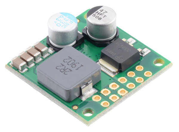
We have a new set of regulators to announce: the D36V50Fx family of step-down voltage regulators. Measuring a compact 1″ × 1″, these regulators support input voltages up to 50 V and can typically deliver around 5 A of current, although some versions can output much more under certain conditions.
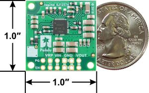 |
Step-Down Voltage Regulator D36V50Fx, bottom view with dimensions. |
|---|
The family consists of six fixed output voltage versions between 3.3 V and 12 V:
- D36V50F3: Fixed 3.3V output
- D36V50F5: Fixed 5V output
- D36V50F6: Fixed 6V output
- D36V50F7: Fixed 7.5V output
- D36V50F9: Fixed 9V output
- D36V50F12: Fixed 12V output
We can also manufacture a customized version for you here in our Las Vegas facility. For example, we could make regulators with a different output voltage that your project needs, or we could replace the 40 V reverse voltage protection MOSFET with a 20 V one for slightly improved efficiency if your input voltage will always be lower than 20 V. If you are interested in customization, please contact us for more information.
Comparison to other regulators
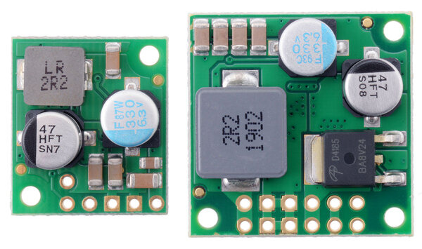 |
D36V28Fx and D36V50Fx Step-Down Voltage Regulators. |
|---|
The D36V50Fx regulators are larger and more powerful counterparts to the D36V28Fx family we introduced last year, with the same input voltage ranges and mostly similar characteristics. What distinguishes the two families in performance is that the D36V50Fx regulators can provide roughly double the output current! (At the high end of the input voltage range, the difference is generally less dramatic.)
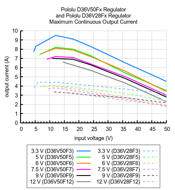 |
Comparison of the maximum continuous current of Step-Down Voltage Regulators D36V50Fx and D36V28Fx. |
|---|
And since many of our most popular regulators are 5 V modules, here is a graph comparing the new D36V50F5 (in blue) with two of our older high-power regulators, the D24V90F5 and the D24V50F5:
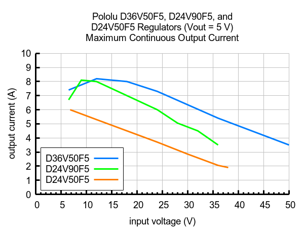 |
Comparison of the maximum continuous current of 5V Step-Down Voltage Regulators D36V50F5, D24V90F5, and D24V50F5. |
|---|
Introductory special
As usual, we are offering an extra introductory special discount on these new regulators, to help share in our celebration of releasing a new product. The first hundred customers to use coupon code D36V50FXINTRO can get up to 3 units of each version for just $11.95 each!
New products: micro metal gearmotors with 15:1 gear ratio
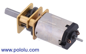 |
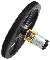
We have expanded our line of micro metal gearmotors to include versions with a 15:1 gear ratio. As with all of our other micro metal gearmotors, these units are available with five different motor options:
 |
- Motors with precious metal brushes
- Motors with longer-life carbon brushes (HPCB)
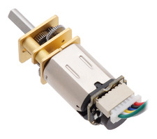
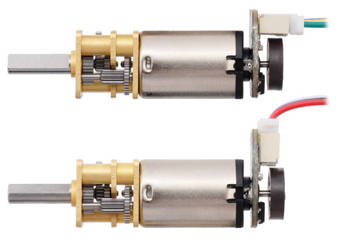
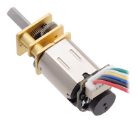
Each motor is available with or without an extended back shaft, which rotates at the same speed as the input to the gearbox and offers a way to add an encoder, such as our encoders for micro metal gearmotors (see the picture above). This makes ten new versions in all:
| Rated Voltage |
Motor Type |
Stall Current (A) |
No-Load Current (A) |
No-Load Speed (RPM) |
Extrapolated Stall Torque |
Max Power (W) |
 Single-Shaft (Gearbox Only) |
 Dual-Shaft (Gearbox & Motor) |
|
|---|---|---|---|---|---|---|---|---|---|
| (kg ⋅ cm) | (oz ⋅ in) | ||||||||
| 12 V | high-power, carbon brushes (HPCB) |
0.75 | 0.06 | 2200 | 0.25 | 3.5 | 1.4 | 15:1 HPCB 12V | 15:1 HPCB 12V dual-shaft |
| 6 V | high-power, carbon brushes (HPCB) |
1.5 | 0.10 | 2100 | 0.25 | 3.5 | 1.3 | 15:1 HPCB 6V | 15:1 HPCB 6V dual-shaft |
| 6 V | high-power (HP) |
1.6 | 0.07 | 2000 | 0.30 | 4.2 | 1.5 | 15:1 HP 6V | 15:1 HP 6V dual-shaft |
| 6 V | medium-power (MP) |
0.67 | 0.04 | 1400 | 0.20 | 2.8 | 0.70 | 15:1 MP 6V | 15:1 MP 6V dual-shaft |
| 6 V | low-power (LP) |
0.36 | 0.02 | 860 | 0.17 | 2.4 | 0.37 | 15:1 LP 6V | 15:1 LP 6V dual-shaft |
More detailed specifications for all our micro metal gearmotors can be found in their datasheet (5MB pdf).
These new versions bring our total micro metal gearmotor selection to 130 options, with gear ratios ranging from 5:1 to 1000:1! To see them all, visit our micro metal gearmotor category, and visit our metal gearmotor category to see all of our metal gearmotor options. Keep in mind if you don’t see an option that suits your application, for sufficient volumes, modifications such as customized output shafts are available.
Once you find the perfect gearmotors for your project, don’t forget to check out our great selection of accessories. These were all designed either specifically for our micro metal gearmotors or with their compatibility in mind:
- Wheels and tracks
- Universal mounting hubs with #2-56, #4-40, or M3 holes.
- 12mm Hex Wheel Adapter for 3mm Shaft
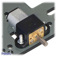
- Mounting brackets in white, black, or extended options
- Magnetic and optical encoders
|
|
|
Our sale has ended, but visit our specials category for great deals all year long!
 |
Our Black Friday Sale has come to an end. As we ship out the last of our Cyber Monday orders, we’d like to point out our Specials category where you can find great deals on Pololu products any time of the year! For the last couple years, we’ve released most of our new products with special intro coupons. If you see a product’s intro banner listed in the specials category, its intro coupon is still active! There’s lots of great deals waiting to be used up, so make sure to have a look before you place your next order!
Our Black Friday/Cyber Monday sale has started!
Our Black Friday / Cyber Monday sale is going strong, and we have been working hard to make and ship the products that people are getting great deals on. Most of the sale coupons can be used on backorders if we happen to run out of stock, but you should still get your orders in early since lead times on some popular products can get long.
Please note that our usual same-day shipping guarantee is suspended during the sale, though so far we have been able to keep up with orders as they have been coming in, and we are closed Thursday, Nov 28th (tomorrow) for Thanksgiving. Happy Thanksgiving!
Design your personalized Black Friday doorbusters
26 November Update: We are no longer accepting doorbuster submissions. If you submitted wishes for doorbuster coupons, thank you! You should receive an email from us soon. All the sale details are now up on the Black Friday sale page.
New product: Pololu 400-Point Breadboard with Mounting Holes
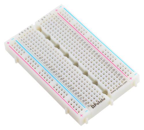 |
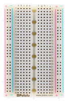
What’s this? A 400-Point breadboard with mounting holes! We know you’ve been waiting for this your whole life.
Okay, maybe not. But hey, mounting holes are awesome, and now you can pick up some of our new 400-point breadboards and mount them all over the place!
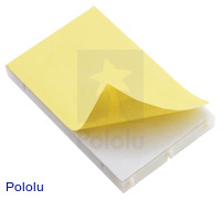
This 3.2″ × 2.1″ breadboard is fairly standard in many ways. It has four bus lines spanning the length of the board and 30 rows of pins, enough for up to four 14-pin DIP ICs or three 16-pin DIP ICs. The rows and columns of tie points are conveniently labeled, multiple units can be connected for larger projects, and it has an adhesive backing for those of you who like sticking breadboards on things.
|
|
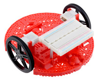
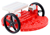
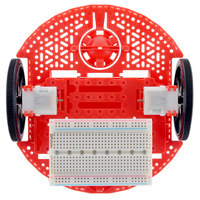
But this breadboard is also a little special. It has eight mounting holes for M2 or #2 screws spaced evenly down the center on a 1 cm pitch. Now you can do stuff like mount your breadboard to a Romi Chassis (or any robot chassis) with some standoffs like this:
|
|
|
Wow! So convenient! And they’re just $2.49 each! But, even better, we’ve got a special discounted price for the first hundred customers. Get up to 10 boards at just $1.75 each using coupon code 400PTBBINTRO!
New products: Magnetic Encoder Pair Kit with JST SH-type Connectors for Micro Metal Gearmotors
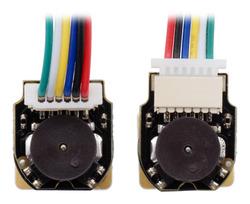 |
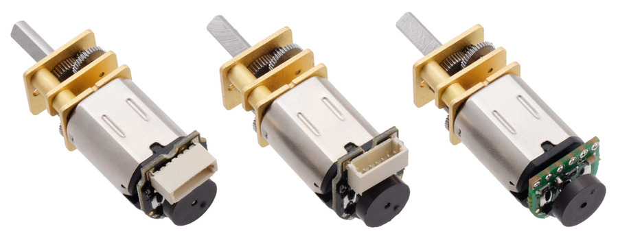
Everyone wants encoders on their motors, but not everyone wants to solder a bunch of wires to a tiny encoder board. That is why I am excited to announce that we are now offering two new versions of magnetic encoders for Micro Metal Gearmotors that feature JST SH-type connectors:
- Magnetic Encoder Pair Kit with Top-Entry Connector for Micro Metal Gearmotors, 12 CPR, 2.7-18V
- Magnetic Encoder Pair Kit with Side-Entry Connector for Micro Metal Gearmotors, 12 CPR, 2.7-18V
These encoders are easier to get up and running than our previous design that requires soldering to through-holes with a 2 mm pitch. With these new encoders, you just have to solder the board to the two motor tabs (sorry, that part is not going away yet), put the magnetic disc on the backshaft, and plug in your cable (available separately in a variety of lengths)!
We think that the “micro” aspect of our Micro Metal Gearmotors is one of their coolest features since their small size make them useful in a wide array of projects. We designed these encoders with this in mind, making them within the profile of the gearmotor on three sides (the side with the connector extends a few millimeters past the motor). Since everyone’s constraints are different, we decided to make two encoder versions, one with a top-entry connector that lets the cable come straight out of the back, and one with a side-entry connector for applications where there isn’t much space past the rear of the motor. We are also continuing to offer encoder boards with through-holes, which allow wires to be soldered to the board for especially compact installations.
|
|
Remember that you will also need 6-pin female JST SH-style cables to use our new encoders. We are offering those cables in three lengths: 12 cm, 30 cm, and 75 cm.
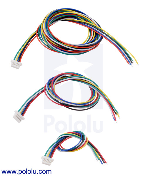 |
The ends of our cables are unterminated so you can decide how you want to connect them in your project (solder, crimp connectors, terminal blocks, etc.).
Introductory special
In case you are not as excited as I am yet, our intro special might help. Right now, you can get up to five of our new encoder pair kits for just $4.95 each using the coupon code MMGMENCINTRO! (Click to add the coupon code to your cart.) But you better hurry, this offer is limited to the first hundred customers to use the coupon code.
Polo-BOO! Halloween Sale
Looking to make an awesome Halloween costume or impressive yard display? Well, we want to help, so we’re having a sale through Wednesday, October 23 on hundreds of items you can use to make things that will impress or terrify your friends and neighbors! Visit the sale page for more information, and if you are in need of some inspiration, check out our Halloween-tagged blog posts for some sample projects.
By the way, we’d love to see more about the amazing things you all are building with our products, so please don’t hesitate to share them with us.
New product: Toshiba TB67S128FTG stepper driver carrier
Our wide selection of stepper motor drivers has grown once again, this time with the addition of a full breakout board for Toshiba’s TB67S128FTG. The TB67S128FTG has many of the same great innovative features as the TB67S2x9FTG carriers we released last year, including Active Gain Control (AGC) for automatically reducing the current when full torque is not needed and Advanced Dynamic Mixed Decay (ADMD) for smoother, more even microsteps. On top of that, it adds features such as microstepping down to 1/128th-step and an optional serial interface. The driver offers a wide operating voltage range of 6.5 V to 44 V, and it can deliver 2.1 A per phase continuous (5 A peak) on our carrier board without any heat sink or forced air flow, making it our highest-current integrated driver (bested only by our discrete MOSFET High-Power Stepper Motor Driver 36v4).
These stepper motor driver carriers first debuted at Toshiba’s booth at Maker Faire Tokyo in August, and now that we finally have the drivers in volume, we are able to offer them to you! All of the driver’s control pins and outputs are available, so it can function as a complete evaluation board for the TB67128FTG, yet it is compact enough to integrate into actual projects without taking up an excessive amount of space:
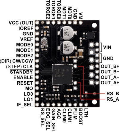 |
TB67S128FTG Stepper Motor Driver Carrier, top view with labeled pinout. |
|---|
Introductory special
As with all of our new product announcements, we are offering an introductory discount to make it extra easy to try out this new driver. Be among the first 100 customers to use coupon code TB67S128INTRO (click to add the coupon code to your cart) and up to three units for just $7.95 each.
New products: ACHS-7124/7125 current sensor carriers
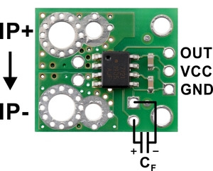 |
We have expanded our line of Hall effect-based linear current sensors from Broadcom to include ±40 A and ±50 A versions. These easy-to-use bidirectional current sensors are now available in five current range options:
- ACHS-7121 Current Sensor Carrier -10A to +10A
- ACHS-7122 Current Sensor Carrier -20A to +20A
- ACHS-7123 Current Sensor Carrier -30A to +30A
- ACHS-7124 Current Sensor Carrier -40A to +40A
- ACHS-7125 Current Sensor Carrier -50A to +50A
With these additions, our full line of current sensors now includes 15 options with current and sensitivity ratings ranging from ±5 A with 400 mV/A sensitivity to ±75 A with 28 mV/A sensitivity. The following table shows all of current sensor options:
 ACS709 Current Sensor Carrier |
 ACS711EX Current Sensor Carriers |
 ACS714 Current Sensor Carriers |
 ACS724 Current Sensor Carriers |
 ACHS-712x Current Sensor Carriers |
|||||||
|---|---|---|---|---|---|---|---|---|---|---|---|
| Sensor IC: | ACS709 | ACS711EX | ACS714 | ACS724 | ACHS-712x | ||||||
| Current range / sensitivity(1): | ±75 A / 28 mV/A | ±15.5 A / 136 mV/A ±31 A / 68 mV/A |
±5 A / 185 mV/A ±30 A / 66 mV/A |
0–10 A / 400 mv/A 0–30 A / 133 mV/A ±5 A / 400 mV/A ±20 A / 100 mV/A ±50 A / 40 mV/A |
±10 A / 185 mV/A ±20 A / 100 mV/A ±30 A / 66 mV/A ±40 A / 50 mV/A ±50 A / 40 mV/A |
||||||
| Path resistance: | 1.1 mΩ | 0.6 mΩ | 1.2 mΩ | 1.2 mΩ | 0.7 mΩ | ||||||
| Bandwidth | 120 kHz | 100 kHz | 80 kHz | 120 kHz | 80 kHz | ||||||
| Vcc range:(1) | 3 V–5.5 V | 3 V–5.5 V | 4.5 V–5.5 V | 4.5 V–5.5 V | 4.5 V–5.5 V | ||||||
| Size: | 0.82″ × 0.9″ | 0.7″ × 0.8″ | 0.7″ × 0.8″ | 0.7″ × 0.8″ | 0.7″ × 0.8″ | ||||||
| Special features: | configurable over-current threshold, low-voltage operation, high bandwidth |
over-current fault pin, low-voltage operation |
Differential Hall sensing rejects common-mode fields, high bandwidth |
||||||||
| 1-piece price: | $5.95 | $3.49 | $19.95 | $6.95 | $3.95 | ||||||
| 1 Sensitivity based on when Vcc is 5V. | |||||||||||
Introductory special
As usual, we are offering an extra introductory special discount on the ACHS-712x current sensor carriers, to help share in our celebration of releasing a new product. The first hundred customers to use coupon code ACHSINTRO can get up to five units for just $3 each!
