Pololu Blog »
Pololu Blog (Page 2)
Welcome to the Pololu Blog, where we provide updates about what we and our customers are doing and thinking about. This blog used to be Pololu president Jan Malášek’s Engage Your Brain blog; you can view just those posts here.
Popular tags: community projects new products raspberry pi arduino more…
Memorial Day sale going on now!

We’re having a big Memorial Day Sale that includes over 1000 products from robots to regulators to sensors to motors, and more! Check out the sale page for more information. Please note that we will be closed Monday, so orders placed after 2 PM Pacific Time Friday, May 23 will be shipped on Tuesday, May 27.
Pololu laser-cut parts used by middle school team at the FIRST LEGO League championships
 |
Last week, 7th-grade robotics team ‘Lightning Strikes Twice!’ (LS2!) from Aspen Middle School in Colorado joined 160 teams from 66 countries to compete in the FIRST LEGO League Challenge World Festival held in Houston, Texas. It was their first time qualifying after winning multiple first-place awards at an event in Fort Collins, Colorado last November, and second place at the Colorado State Championship in December.
LS2! designed an autonomous turtle robot to conduct coral reef research, which uses LEGO electronics and pieces to control the flipper mechanism. Pololu supported the team with laser-cut plywood pieces for mounting the paddles and acrylic pieces for the tail and watertight body with gasketed openings.
 |
Turtle robot SHELTN2 submerged in a swimming pool. |
|---|
Working with Pololu was great. The parts arrived quickly and were very well packed. I suggested the students leave 3 mm of clearance around the LEGO structure to account for tolerance in the laser cutting and assembly but the parts were very accurate so we could have made it tighter. We used a combination of Weld-On 4 and 16 to glue the acrylic. The most challenging part was designing for the rubber shift boots we used to seal the joints while allowing movement. SHELTN’s total weight was approximately 7 kg plus 6 kg of ballast to achieve neutral buoyancy.
- William Gilmore, Mentor, Lightning Strikes Twice!

You can read more about the FIRST Championship in Houston in this FIRST press release, and visit the FIRST LEGO League blog for a full list of challenge and division award recipients.
We’re proud that parts from our Custom Laser Cutting Service helped LS2! bring their design to life and excel through their competition. Congrats to Lightning Strikes Twice! on all of their achievements!
Related products

New products: Pololu Isolated Solid State Relay/Switch, SPST
 |
We’re happy to announce our new Isolated Solid State Relay/Switch boards! These modules function as solid state, single-pole, single-throw (SPST) relays or switches that can be controlled by low-current signals between 2.7 V and 40 V. The control signal activates an optically coupled driver that turns on a pair of output MOSFETs, which keeps the outputs electrically isolated from the input side. The MOSFETs are arranged back-to-back to make the outputs symmetric and bidirectional (so the board can be used as a high-side or low-side switch).
 |
These boards make good replacements for mechanical relays in many situations, since their semiconductor-based design allows them to avoid problems like contact wear and arcing that limit the service life of mechanical relays. They are also silent and generally much smaller than a typical mechanical relay with a comparable current rating. Two versions of the solid state relay/switch are available with different voltage and current capabilities:
- Pololu Isolated Solid State Relay/Switch, SPST, 30V, 11A
- Pololu Isolated Solid State Relay/Switch, SPST, 60V, 7A
 |
Three-wire and two-wire (with EN and VIN tied together) control options for the Pololu Isolated Solid State Relay/Switch, SPST (60V version shown). |
|---|
Introductory special discount! Use coupon code SSRELAYINTRO to get either version for $3.50 each.
Related products


More new current sensors!
 |
 |
|
|


We have released even more current sensors! As with our assortment of other active and preferred current sensors, these new boards are based on Allegro current-sensing ICs and have analog outputs with voltage proportional to the AC or DC current passing through the sensor while offering full electrical isolation of the current path from the sensor’s electronics. This isolation allows them to be inserted anywhere in the current path, including on the high side, and because the current path resistance is on the order of 2 mΩ or less, there is minimal effect on the rest of the system. Here’s a quick summary of the new sensor families:
Allegro ACS37041/ACS37042
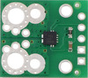
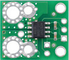
These low-cost bidirectional current sensors have ranges of -10 A to +10 A or -30 A to +30 A with dedicated versions for 3.3 V and 5 V systems. The sensor itself is a tiny 5-pin SOT-23 package, which allows for an extra-compact, “micro” carrier board that is approximately 1/5th the size of our next smallest current sensor carrier. We also have versions in our standard “compact” form factor, which for these sensors end up being the larger of the two form factors available. These larger versions can accommodate a wider variety of connectors and thicker wires, and they have the same overall dimensions and current-path mounting hole arrangements as our other “compact” current sensor carriers.
|
|
||
|
|


The ACS37041 and ACS37042 are almost identical, with the key difference being that the ACS37042 has a higher isolation voltage rating. To support operation at higher voltages, the carrier boards for the ACS37042 versions have routed slots for higher creepage distances along the PCB surface. The pictures above show the ACS37041 carriers on the left and the ACS37042 carriers on the right.
The following table shows all of our ACS37041 and ACS37042 carrier options:
| Pololu Item # |
Part Suffix | Isolation Rating 1 |
Supply Voltage | Current Range |
Sensitivity (mV/A) |
Zero Point | Size | PCB Details |
Min PCB Creepage 2 |
Price | |
|---|---|---|---|---|---|---|---|---|---|---|---|
| ACS3704x Micro Carriers | |||||||||||
 ACS37041 |
#5440 (coming June 2025) | 010B3 | 100 VRMS | 3.0 V to 3.6 V | ±10 A | 132 | 1.65 V | 0.3″×0.4″ 7.6×10.2 mm |
2 layers, 1-oz copper |
1.6 mm | $4.15 |
| #5441 | 030B3 | ±30 A | 44 | ||||||||
| #5442 | 010B5 | 4.5 V to 5.5 V | ±10 A | 200 | 2.5 V | ||||||
| #5443 | 030B5 | ±30 A | 66.7 | ||||||||
 ACS37042 |
#5450 | 010B3 | 285 VRMS | 3.0 V to 3.6 V | ±10 A | 132 | 1.65 V | 2.0 mm | $4.69 | ||
| #5451 | 030B3 | ±30 A | 44 | ||||||||
| #5452 (coming June 2025) | 010B5 | 4.5 V to 5.5 V | ±10 A | 200 | 2.5 V | ||||||
| #5453 (coming June 2025) | 030B5 | ±30 A | 66.7 | ||||||||
| ACS3704x Compact Carriers | |||||||||||
 ACS37041 |
#5444 (coming June 2025) | 010B3 | 100 VRMS | 3.0 V to 3.6 V | ±10 A | 132 | 1.65 V | 0.7″×0.8″ 17.8×20.3 mm |
2 layers, 2-oz copper |
1.6 mm | $4.45 |
| #5445 | 030B3 | ±30 A | 44 | ||||||||
| #5446 | 010B5 | 4.5 V to 5.5 V | ±10 A | 200 | 2.5 V | ||||||
| #5447 | 030B5 | ±30 A | 66.7 | ||||||||
 ACS37042 |
#5454 | 010B3 | 285 VRMS | 3.0 V to 3.6 V | ±10 A | 132 | 1.65 V | 3.0 mm | $4.99 | ||
| #5455 | 030B3 | ±30 A | 44 | ||||||||
| #5456 (coming June 2025) | 010B5 | 4.5 V to 5.5 V | ±10 A | 200 | 2.5 V | ||||||
| #5457 (coming June 2025) | 030B5 | ±30 A | 66.7 | ||||||||
| Note 1: IC component rating per manufacturer datasheet. | |||||||||||
| Note 2: Minimum creepage along PCB surface based on layout design only. Other creepage distances, e.g. along the body of the component, may be lower. | |||||||||||
Allegro ACS37030
These sensors measure bidirectional currents from -20 A to +20 A or -65 A to +65 A, and they are intended for 3.3 V systems. What makes them really special are their extra-low (40 ns typical) response times and extra-high 5 MHz bandwidth, which are made possible by their combined use of two sensing technologies: a Hall effect sensor captures DC and low-frequency current information and an inductive coil captures high-frequency signals. The following table shows our available options:
| Pololu Item # |
Part Suffix | Supply Voltage | Current Range |
Sensitivity (mV/A) |
Zero Point | Size | PCB Details |
Price | |
|---|---|---|---|---|---|---|---|---|---|
| ACS37030 Compact Carriers | |||||||||
 |
#5230 | 020B3 | 3.0 V to 3.6 V | ±20 A | 66 | 1.65 V | 0.7″×0.8″ 17.8×20.3 mm |
2 layers, 2-oz copper |
$11.95 |
| #5231 (coming July 2025) | 040B3 | ±40 A | 33 | ||||||
| #5232 | 065B3 | ±65 A | 20.3 | ||||||
| ACS37030 Large Carriers | |||||||||
 |
#5235 | 065B3 | 3.0 V to 3.6 V | ±65 A | 20.3 | 1.65 V | 1.4″×1.2″ 35.6×30.5 mm |
6 layers, 2-oz copper |
$14.95 |
| #5236 (coming July 2025) | 040B3 | ±40 A | 33 | ||||||
These sensors are available in our standard compact form factor, which is great for use in space-constrained systems, and the higher-current versions are also available in our standard large form factor, which supports more connection options for higher-current applications. The large carriers offer better thermal dissipation thanks to their 6-layer PCBs and increased surface area, and the holes and slots for the current path connection points accommodate thicker wires along with a variety of high-current connectors (e.g. lugs, solderless ring terminals, and 4-pin terminal blocks). Having these standard form factors available makes it easier to swap among different boards to compare different sensor ICs, and having different form factors available for the same sensor IC also makes it possible to evaluate how things like PCB area and the number of copper layers affects the sensor’s thermal performance
All our current sensors
These new additions bring us up to 96 total active and preferred current sensor carriers! Here’s a handy table comparing them all:
 |
 |
 |
 |
 |
 |
 |
 |
 |
 |
 |
 |
 |
|
|---|---|---|---|---|---|---|---|---|---|---|---|---|---|
| ACS3704x Current Sensor Micro Carriers |
ACS3704x Current Sensor Compact Carriers |
ACS711 Current Sensor Carriers |
ACS71240 Current Sensor Carriers |
ACS724 Current Sensor Carriers |
ACS37220 Current Sensor Compact Carriers |
ACS37220 Current Sensor Large Carriers |
ACS37030 Current Sensor Compact Carriers |
ACS37030 Current Sensor Large Carriers |
ACS72981 Current Sensor Compact Carriers |
ACS72981 Current Sensor Large Carriers |
CT432/CT433 TMR Current Sensor Compact Carriers |
CT432/CT433 TMR Current Sensor Large Carriers |
|
| Allegro Sensor | ACS3704x | ACS711KEXT | ACS71240 | ACS724LLCTR | ACS37220 | ACS37030 | ACS72981xLR | CT432/CT433 | |||||
| Sensing technology | Hall effect | Hall effect | Hall effect | Hall effect | Hall effect | Hall effect + inductive coil | Hall effect | XtremeSense™ TMR (tunneling magnetoresistance) |
|||||
| Logic voltage range | 3.3V versions: 3.0–3.6 V 5V versions: 4.75–5.5 V |
3.0–5.5 V | 3.3V ver: 3.0–3.6 V 5V ver: 4.5–5.5 V |
4.5–5.5 V | 3.3V versions: 3.15–3.45 V 5V versions: 4.5–5.5 V |
3.0–3.6 V | 3.3V versions: 3.0–3.6 V 5V versions: 4.5–5.5 V |
3.3V versions: 3.0–3.6 V 5V versions: 4.75–5.5 V |
|||||
| Family current range | 10–30 A | 15.5–31 A | 10–50 A | 2.5–50 A | 100–200 A | 20–65 A | 50–200 A | 20–70 A | |||||
| Current range/ sensitivity of individual versions |
ACS37041: 3.3V Bidirectional: ±30 A / 44 mV/A 5V Bidirectional: ±10 A / 200 mV/A ±30 A / 66.7 mV/A ACS37042: 3.3V Bidirectional: ±10 A / 132 mV/A ±30 A / 44 mV/A |
ACS37041: 3.3V Bidirectional: ±30 A / 44 mV/A 5V Bidirectional: ±10 A / 200 mV/A ±30 A / 66.7 mV/A ACS37042: 3.3V Bidirectional: ±10 A / 132 mV/A ±30 A / 44 mV/A |
Bidirectional:(1) ±15.5 A / 90 mV/A ±31 A / 45 mV/A |
3.3V Bidirectional: ±10 A / 132 mV/A ±30 A / 44 mV/A ±50 A / 26.4 mV/A 5V Bidirectional: ±10 A / 200 mV/A ±30 A / 66 mV/A ±50 A / 40 mV/A 5V Unidirectional: 0–50 A / 80 mv/A |
5V Bidirectional:(2) ±2.5 A / 800 mV/A ±5 A / 400 mV/A ±10 A / 200 mV/A ±20 A / 100 mV/A ±30 A / 66 mV/A ±50 A / 40 mV/A 5V Unidirectional:(2) 0–5 A / 800 mv/A 0–10 A / 400 mv/A 0–20 A / 200 mv/A 0–30 A / 133 mV/A |
3.3V Bidirectional: ±100 A / 13.2 mV/A ±150 A / 8.8 mV/A 5V Bidirectional: ±100 A / 20 mV/A ±150 A / 13.3 mV/A ±200 A / 10 mV/A |
3.3V Bidirectional: ±100 A / 13.2 mV/A ±150 A / 8.8 mV/A 5V Bidirectional: ±100 A / 20 mV/A ±150 A / 13.3 mV/A ±200 A / 10 mV/A |
3.3V Bidirectional: ±20 A / 66 mV/A ±65 A / 20.3 mV/A |
3.3V Bidirectional: ±65 A / 20.3 mV/A |
3.3V Bidirectional:(1) ±50 A / 26.4 mV/A ±100 A / 13.2 mV/A ±150 A / 8.8 mV/A ±200 A / 6.6 mV/A 3.3V Unidirectional:(1) 0–50 A / 52.8 mv/A 0–100 A / 26.4 mv/A 0–150 A / 17.6 mv/A 0–200 A / 13.2 mv/A 5V Bidirectional:(2) ±50 A / 40 mV/A ±100 A / 20 mV/A ±150 A / 13.3 mV/A ±200 A / 10 mV/A 5V Unidirectional:(2) 0–50 A / 80 mv/A 0–100 A / 40 mv/A 0–150 A / 26.7 mv/A |
3.3V Bidirectional:(1) ±50 A / 26.4 mV/A ±100 A / 13.2 mV/A ±150 A / 8.8 mV/A ±200 A / 6.6 mV/A 3.3V Unidirectional:(1) 0–50 A / 52.8 mv/A 0–100 A / 26.4 mv/A 0–150 A / 17.6 mv/A 0–200 A / 13.2 mv/A 5V Bidirectional:(2) ±50 A / 40 mV/A ±100 A / 20 mV/A ±150 A / 13.3 mV/A ±200 A / 10 mV/A 5V Unidirectional:(2) 0–50 A / 80 mv/A 0–100 A / 40 mv/A 0–150 A / 26.7 mv/A |
3.3V Bidirectional: ±20 A / 50 mV/A ±30 A / 33.3 mV/A ±50 A / 20 mV/A ±70 A / 14.3 mV/A 3.3V Unidirectional: 0–20 A / 100 mv/A 0–30 A / 66.7 mv/A 0–50 A / 40 mv/A 0–65 A / 30.8 mv/A 5V Bidirectional: ±20 A / 100 mV/A ±30 A / 66.7 mV/A ±50 A / 40 mV/A ±65 A / 30.8 mV/A 5V Unidirectional: 0–20 A / 200 mv/A 0–30 A / 133.3 mv/A 0–50 A / 80 mv/A 0–70 A / 57.1 mv/A |
3.3V Bidirectional: ±50 A / 20 mV/A ±70 A / 14.3 mV/A 3.3V Unidirectional: 0–50 A / 40 mv/A 0–65 A / 30.8 mv/A 5V Bidirectional: ±50 A / 40 mV/A ±65 A / 30.8 mV/A 5V Unidirectional: 0–50 A / 80 mv/A 0–70 A / 57.1 mv/A |
| IC current path resistance | 1.6 mΩ | 0.6 mΩ | 0.6 mΩ | 0.6 mΩ | 0.1 mΩ | 0.7 mΩ | 0.2 mΩ | 1 mΩ | |||||
| PCB | 2 layers, 1-oz copper |
2 layers, 2-oz copper |
2 layers, 2-oz copper |
2 layers, 2-oz copper |
2 layers, 2- or 4-oz copper(4) |
2 layers, 2-oz copper |
6 layers, 2-oz copper |
2 layers, 2-oz copper |
6 layers, 2-oz copper |
6 layers, 2-oz copper |
6 layers, 2-oz copper |
2 or 4 layers(5), 2-oz copper |
6 layers, 2-oz copper |
| Max bandwidth | 150 kHz | 100 kHz | 120 kHz | 120 kHz(3) | 150 kHz | 5 MHz | 250 kHz | 1 MHz | |||||
| Size | 0.3″ × 0.4″ | 0.7″ × 0.8″ | 0.7″ × 0.8″ | 0.7″ × 0.8″ | 0.7″ × 0.8″ | 0.7″ × 0.8″ | 1.4″ × 1.2″ | 0.7″ × 0.8″ | 1.4″ × 1.2″ | 0.7″ × 0.8″ | 1.4″ × 1.2″ | 0.8″ × 1.1″ | 1.4″ × 1.2″ |
| Overcurrent fault output |
User-configurable threshold | ||||||||||||
| Common-mode field rejection | |||||||||||||
| Nonratiometric output | |||||||||||||
| 1-piece price | $4.15 | $4.45 | $4.85 | $5.25 | $9.95 – $11.49 | $6.95 | $10.95 | $11.95 | $14.95 | $13.95 | $16.95 | $12.95 | $16.95 |
Note 1: Sensitivity when Vcc = 3.3 V; actual sensitivity is ratiometric (i.e. it is proportional to Vcc).
Note 2: Sensitivity when Vcc = 5 V; actual sensitivity is ratiometric (i.e. it is proportional to Vcc).
Note 3: Bandwidth can be reduced by adding a filter capacitor.
Note 4: 50A version uses 4-oz copper PCB; all other versions use 2-oz copper.
Note 5: 50A and higher versions use a 4-layer PCB; all other versions use a 2-layer PCB.
You can also use the following selection box to see all these options sorted by current range:
Alternatives available with variations in these parameter(s): current range Select variant…
Related products


April 12, 2025 tariff update and new price change notification feature
As a small US-based electronics manufacturer, we have been contemplating tariffs a lot this year, especially over the last several weeks, when our mindset changed from primarily “let’s see what happens” to more of “this could be an existential threat and we need to act right away.” Like much of the world, we were shocked by the April 2 announcement of new, and high, US tariffs on seemingly everything from everywhere and the subsequent dramatic escalation of tariffs on China, which are up to 145%, or maybe 170% or 195% on some electronics components, as I write this on Saturday, April 12.
With the various pauses and extensions and exemptions that are announced almost daily, it might seem that the tariffs are just talk, but we have been getting hit by tariffs of 45-70% on electronics components for the past several months already. Often, these are for integrated circuits that we ordered months ago and that can ship from various countries, and we find out about the extra 70% cost only after we receive the parts. This summary from a recent Arrow Electronics order for some stepper motor driver ICs shows Arrow trying to get ahead of the tariff shocks and how high their estimate had gotten (I am not sure how they are calculating it, and it probably also changes day to day):
 |
Order summary from an April 6 stepper motor driver chip order showing estimated tariff of 144%. |
|---|
We just finally mostly recovered from the pandemic-era chip shortages, and we don’t want to wait too long on reacting as we did then, when some of our key stock was quickly bought up and left us unable to manufacture some products for nearly two years. So, over the past week, we have gone through and assessed the pricing of all of the thousands of products we sell. Since most products have various quantity price breaks and pricing for our distributors, we updated tens of thousands of prices.
Our system is not made for this. When we release products, it’s usually one at a time and we carefully assess our costs and competing products to set what we expect to be good prices. If there are small cost increases over time, we usually absorb them, and if there is a big jump in some component cost, we can reassess and reprice the affected products individually. But here, we are dealing with the sudden, not precisely-specified, and unequal cost change of almost every component. So, the price changes that we have made over the past week have been much less carefully considered and more dependent on formulas based on costs and countries of origin and other data we have available.
Many of the “individual assessments” amounted to looking at prices our programs spit out and seeing if they seemed reasonable, and in many cases we just flagged the item for further review later and accepted the proposed prices or overrode to stick with our old prices. And, in some cases, we had to override to make the prices higher still based on knowing that a particular part was already constrained or getting higher tariffs.
This morning (again, Saturday, April 12) as I started writing this post, I saw news reports that semiconductor devices would be exempted from the latest extra hikes. Even if that applies to the kinds of integrated circuits we use, I think that means the 70% portion that we have already been paying is still staying in place. It’s also not clear to me if things like inductors, which we’re currently paying an extra 45% on are going to stay at 45% or going to 170% or what (basically all commodity inductors in the world come from China as far as I know). Even if they do get some exemptions or the tariffs are walked back more broadly, I suspect the 45% increase will be a new minimum for a while.
These new exemptions announced today should be good news for us, but I find myself feeling deflated as I contemplate more and more effort having to go into constantly repricing everything while looking at bills for extra thousands of dollars in tariffs almost daily. (This post is mostly about the work going into pricing for our customers, but there is also lots of decision making about what to buy now, such as do we get extra material now before prices go up more, or do we hold out hoping for them to go down and risk running out of components? Will the demand still be there for a product if it’s more expensive? And so on.)
Anyway, the point of this post is not to whine or wallow or complain, but rather to give our customers and partners some idea of how we are dealing with the tariffs. Price increases are not pleasant, and we are working on keeping them to a minimum and reducing prices again when we can. We are also quickly developing a new price change notification feature on our website so that you can be notified of price changes on any products you care about:
 |
New price change notification feature. |
|---|
Because things are changing so quickly, we are rolling out this new website feature and I am announcing it before we have the notification email system implemented, so it might be a while before we can start sending out the notifications. I am thinking that until we have it all working and until things stabilize, this can also be a way for us to get feedback about which products might have been badly repriced and that we should prioritize for reassessment.
Please reach out and share your thoughts in the older established ways, too. Especially if you are a customer wondering about the future of some product, please let us know your concerns and we will do our best to give you whatever insight we might have and work with you on prices.
New products: Isolated USB-to-I²C Adapters
 |
We’re excited to introduce our new isolated USB-to-I²C adapters! These boards make it easy to control your I²C device from your PC or other USB host, giving your applications access to a world of sensors and actuators or simplifying evaluation and troubleshooting of I²C hardware. Two versions are available, one that requires VCC to be supplied separately to the I²C side and one that can deliver 5V or 3.3V power to your I²C bus from your USB port while still maintaining electrical isolation.
|
|


Both adapters offer full galvanic isolation to protect your PC from your experimental circuits and to avoid subtle common-ground problems.
 |
Schematic diagram of the Pololu Isolated USB-to-I²C Adapter with Isolated Power. |
|---|
The firmware is open source, so you can customize them, and the galvanic isolation building blocks used in these adapters are available separately in smaller modules if you want to implement your own isolated systems.
Related products


Pololu product on the Moon!
This is not an April fools joke! One of our products is literally on the moon right now, and we got clearance from Firefly Aerospace to share this level of detail:
One of our encoders supported the gimbal mechanisms on the top deck of Firefly Aerospace’s Blue Ghost lunar lander that completed a successful mission on the Moon in March 2025. These mechanisms helped point the X-band antenna back at Earth after landing as shown here:

Learn more about Firefly’s Blue Ghost mission here: Blue Ghost Mission 1 – Firefly Aerospace.
Congratulations to everyone at Firefly Aerospace and thank you for letting us be a part of it!

Finding common ground is for suckers!
|
|


We usually think of ground as a common point in our circuits, and many problems arise from not having a good (or any) ground connection. But there’s also the flip side of unexpected ground connections leading to malfunction or even destruction of our electronics systems. Keeping grounds separated can be an important part of improving functionality and reliability when connecting many parts or boards together, which is why we have continued our push into simplifying electrical isolation with the release of four new I²C isolator boards:
- Pololu I²C Isolator, ISO1640
- Pololu I²C Isolator with Connectors, ISO1640
- Pololu I²C Isolator with Isolated Power, ISO1640, MIE1W0505BGLVH, 5V/3.3V, 200mA
- Pololu I²C Isolator with Isolated Power and Connectors, ISO1640, MIE1W0505BGLVH, 5V/3.3V, 200mA
These modules enable bidirectional I²C communication between devices while maintaining complete galvanic isolation between the two sides. This prevents the unexpected flow of current between the two sides, and it can also prevent destructive voltages on one side from propagating into the other (note that in this scenario one side will still be destroyed, but at least the damage will be contained to the isolated portion). The modules are based on Texas Instruments’ ISO1640B, which supports bidirectional data transfer up to 1.7 MHz. The clock line (SCL) is also bidirectional, which allows for clock stretching.
|
|


Two board versions are available, one with isolated power and one without. The version with isolated power can deliver regulated, isolated power at 3.3 V or 5 V to the target thanks to the incorporation of the MPS MIE1W0505BGLVH (which you might recognize from the standalone power module we released a few months ago), while the simpler version without isolated power requires the two sides to be powered separately.
 |
Schematic diagram of the Pololu I²C Isolator with Isolated Power. |
|---|
Each version is optionally available with JST SH-style 4-pin connectors that are compatible with Qwiic and Stemma QT.
|
|


Introductory special discounts! Use coupon code I2CISOINTRO to get the versions without isolated power for $3.49 and use coupon code P5392P5393INTRO to get the versions with isolated power for $6.49.
Related products


New higher-power reverse voltage protector and ideal diode
 |
We are excited to announce the release of two new higher-power reverse voltage protectors that can handle up to around 25 A continuous while protecting your 4V–60V circuit from accidental destruction from reverse voltage:
- Reverse protection only – This version protects against reverse voltage while still allowing reverse current, making it suitable for applications such as battery-powered motor control where delivering energy back into the battery is desirable.
- Reverse protection with reverse current blocking – This version acts as an ideal diode, preventing current from flowing from output to input.
These boards feature larger 5×6mm MOSFETs with lower on-resistances and more than double the current carrying ability of the versions we released a few months ago, which makes the overall module larger (but still compact!):
 |
60V-max Pololu Reverse Voltage Protectors are available in 20A/25A (left) and 10A/12A (right) versions. |
|---|
With these new releases, we now have six total reverse protector options (with or without reverse current blocking in three different power levels):
| Reverse protection | Max current |
MOSFET on resistance |
Size | Price | Pololu Item # |
|---|---|---|---|---|---|
| Reverse voltage only | 10 A | < 10 mΩ | 0.3″×0.5″ | $3.29 | #5380 |
| 12 A | < 5 mΩ | $4.39 | #5381 | ||
| 25 A | < 1.5 mΩ | 0.435″×0.7″ | $7.95 | #5387 | |
| Reverse voltage and current (ideal diode) |
10 A | < 10 mΩ | 0.3″×0.5″ | $3.79 | #5382 |
| 12 A | < 5 mΩ | $4.95 | #5383 | ||
| 25 A | < 1.5 mΩ | 0.435″×0.7″ | $8.49 | #5389 | |
Introductory special discount! Use coupon code RVP25INTRO to get these new reverse voltage protectors for just $2.95!
Related products


New product: Isolated DC-DC Power Module, MIE1W0505BGLVH, 5V/3.3V, 200mA
 |
I am happy to introduce our first isolated power module, which we expect to kick off a new category of electrical isolation products (note that the many current sensors we carry also feature isolation from the sense side to the control side, but that isolation is part of their more dedicated current-sensing functionality). Many of our products are modules like motor controllers and regulator boards, and connecting several of them together in real-world settings can lead to unexpected problems from connecting all the grounds together. For example, your computer’s USB port can be a convenient source of 5 V, but the negative or ground side of that 5 V will likely be connected to the ground pin of the computer’s power cable and therefore to the ground side of everything else you have plugged into the wall. This can lead to unexpected problems as you build up your system, usually without thinking about your house being part of your circuit.
 |
There are more and more solutions for effectively moving power and signals without having an electrical connection, so we will be working on adding those into our more integrated products, and we will be adding to our isolation module portfolio to support our customers with the building blocks to make safer and more reliable systems themselves.
The module we are introducing today can provide galvanically isolated and regulated 5 V or 3.3 V power at up to 200 mA. It’s based on the MIE1W0505BGLVH from MPS, and it’s amazing how much is integrated into a chip like that, including a transformer to get the power from one side to the other without an electrical connection. Only a few passives are needed to support the IC, allowing our board to be small (0.3″ × 0.6″) and low-cost. It’s easy to use, too, with all the necessary information provided on the product page. The datasheet is available if you want more information, but you can use this module without knowing the details in there. (This is unlike what we call “carrier boards”, which require you to familiarize yourself with the chip.)
 |
Introductory special discount! Use coupon code 5384INTRO to get this new power module for just $2.75!


Home | Forum | Blog | Support | Ordering Information | Lists | Distributors | BIG Order Form | About | Contact
© 2001–2026 Pololu Corporation


