Motion Control Modules » Brushed DC Motor Drivers » Pololu High-Power Motor Drivers »
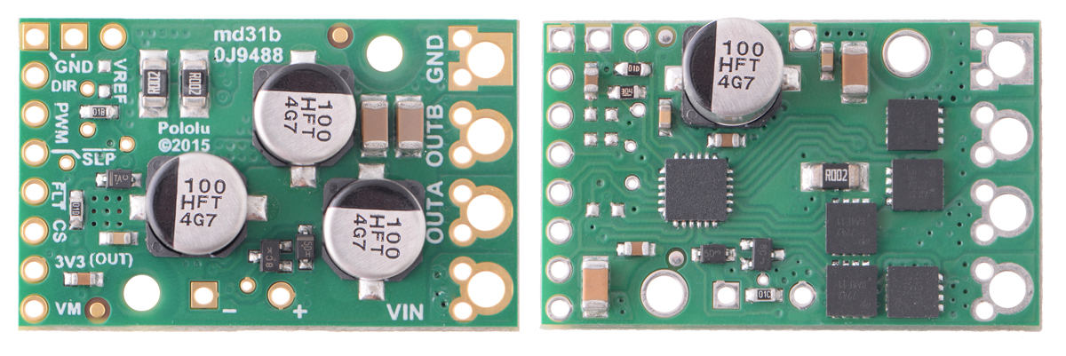
Pololu H2 High-Power Motor Driver 36v11 CS

This discrete MOSFET H-bridge motor driver enables bidirectional control of one high-power brushed DC motor. The small 1.3″ × 0.8″ board supports a wide 5 V to 60 V voltage range and is efficient enough to deliver a continuous 11 A without a heat sink. Additional features include reverse-voltage protection and an on-board current sensor that provides a direct measurement of the motor current.
 Compare all products in Pololu High-Power Motor Drivers or Single-Channel G2 and H2 High-Power Motor Drivers.
| Description | Specs (13) | Pictures (5) | Resources (4) | FAQs (1) | On the blog (0) | Distributors (33) |
|---|
Overview
 |
The Pololu H2 high-power motor driver 36v11 CS is a discrete MOSFET H-bridge designed to drive large brushed DC motors. The H-bridge is made up of one N-channel MOSFET per leg; the rest of the board contains the circuitry to take user inputs and control the MOSFETs. The absolute maximum voltage for this motor driver is 60 V, and higher voltages can permanently destroy the motor driver. Under normal operating conditions, ripple voltage on the supply line can raise the maximum voltage to more than the average or intended voltage, so a safe maximum voltage is approximately 48 V.
Note: Battery voltages can be much higher than nominal voltages when they are charged, so the maximum nominal battery voltage we recommend is 36 V (and use with 48 V batteries is not recommended) unless appropriate measures are taken to limit the peak voltage.
The versatility of this driver makes it suitable for a large range of currents and voltages: it can deliver up to 11 A of continuous current with a board size of only 1.3″ × 0.8″ and no required heat sink. The module offers a simple interface that requires as few as two I/O lines, and an on-board current sensor gives a direct measurement of motor current. The power supply inputs feature reverse-voltage protection, while integrated detection of various fault conditions helps protect against other common causes of catastrophic failure; however, please note that the board does not include over-temperature protection. We recommend you use the integrated current sensor to keep the driver from delivering more current than it can safely handle.
Features and specifications
- H-bridge motor driver: can drive one bidirectional brushed DC motor
- Operating voltage: 5 V to 60 V (absolute maximum)
- Maximum continuous output current: 11 A
- Inputs compatible with 3.3 V, and 5 V logic
- On-board current sensor directly measures motor current
- Reverse-voltage protection
- Undervoltage shutdown
- Short circuit protection
- Size: 1.3″ × 0.8″
- Two 0.086″ mounting holes for #2 or M2 screws
G2 and H2 high-power motor driver versions
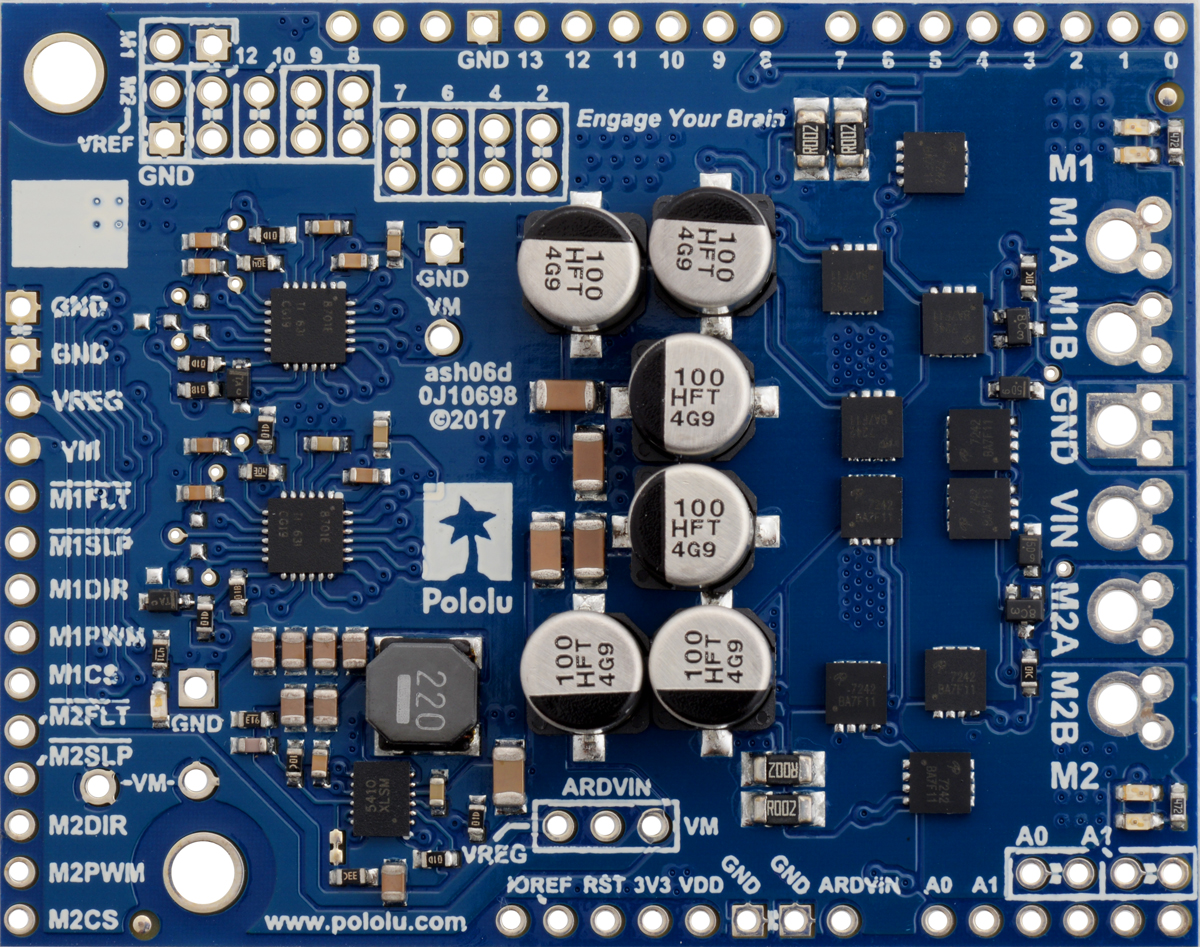
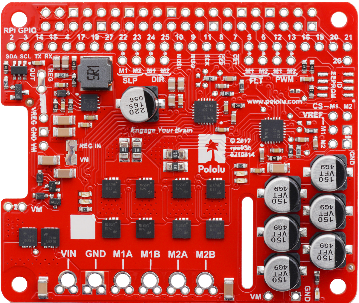
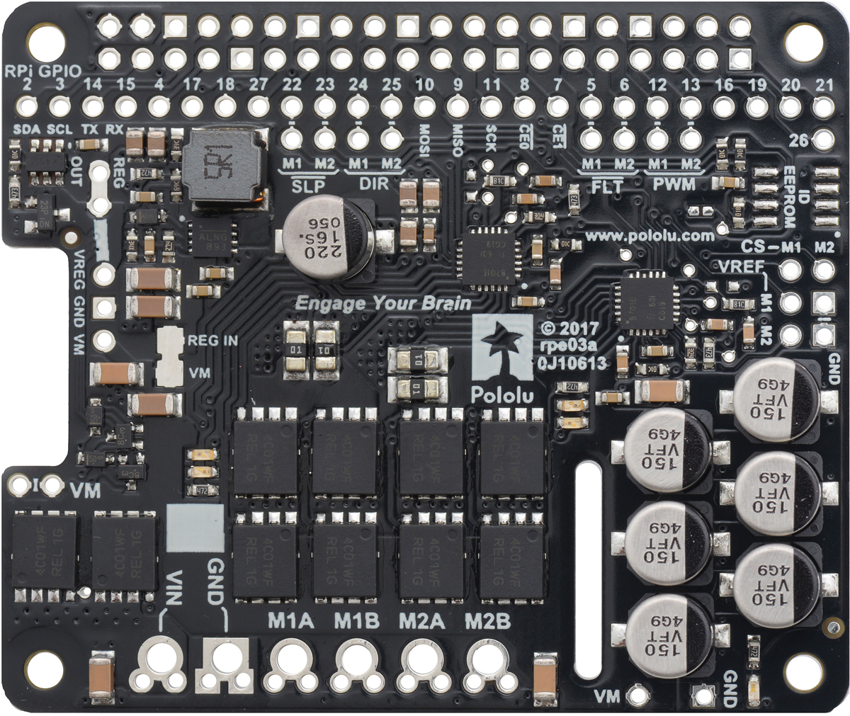
The following table provides a general comparison of the G2 and H2 drivers, which are available in six single-channel versions and eight dual-channel versions. Four of the dual-channel drivers have the form factor of an Arduino shield, but they can also be used with other controllers as general-purpose motor drivers. The other four dual-channel drivers are in the form factor of a Raspberry Pi HAT and compatible Raspberry Pi boards (Model B+ or newer). The single-channel G2 drivers all have the same form factor except for the highest-power 24v30, which is larger to accommodate the much larger MOSFETs. We also have a higher-voltage, single-channel H2 high-power motor driver with the same form factor as the single-channel G2 drivers, but the control interface and some aspects of the operation are different.
| G2 and H2 High-Power Motor Drivers | ||||||||||
|---|---|---|---|---|---|---|---|---|---|---|
 G2 18v17 |
 G2 18v25 |
 G2 24v13 |
 G2 24v21 |
 G2 24v30 CS |
 H2 36v11 CS |
 G2 18v18 |
 G2 18v22 |
 G2 24v14 |
 G2 24v18 |
|
| Motor channels | single (1) | dual (2) | ||||||||
| Min. operating voltage | 6.5 V | 5 V | 6.5 V | |||||||
| Absolute max. input voltage | 30 V | 40 V | 60 V | 30 V | 40 V | |||||
| Max. nominal battery voltage | 18 V | 28 V | 36 V | 18 V | 28 V | |||||
| Max. continuous current(1) | 17 A | 25 A | 13 A | 21 A | 30 A | 11 A | 18 A | 22 A | 14 A | 18 A |
| Current sense feedback | 20 mV/A | 10 mV/A | 40 mV/A | 20 mV/A | 13.2 mV/A | 60 mV/A(2) | 20 mV/A | 10 mV/A | 20 mV/A | 20 mV/A |
| Direct motor current measurement |
— | — | — | — | — | — | — | — | ||
| Default current limit(3) | 40 A | 60 A | 30 A | 50 A | 100 A | n/a | 50 A | 60 A | 40 A | 50 A |
| Size | 1.3″ × 0.8″ | 1.7″ × 1.9″ | 1.3″ × 0.8″ | 2.56″ × 2.02″ | ||||||
| Shield version available? | — | — | — | — | — | — | Yes | Yes | Yes | Yes |
| Raspberry Pi expansion version available? |
— | — | — | — | — | — | Yes | Yes | Yes | Yes |
| 1-piece price | $44.95 | $56.95 | $44.95 | $56.95 | $74.95 | $56.95 | $74.95 | $104.95 | $79.95 | $104.95 |
| Note 1: Per motor channel, at room temperature and without heat sinking or forced air flow. | ||||||||||
| Note 2: When VCC = 5 V; sensitivity is proportional to VCC. | ||||||||||
| Note 3: Can be adjusted lower. | ||||||||||
|
|

|
|

|
|
Note: As an alternative to these motor drivers, our Simple Motor Controllers have similar power characteristics and offer high-level interfaces (e.g. USB, RC hobby servo pulses, analog voltages, and TTL serial commands) that make them easier to use for some applications.
Using the motor driver
Pinout
 |
| PIN | Default State | Description |
|---|---|---|
| VIN | This is the main 5 V to 60 V (absolute max) motor power supply connection. | |
| GND | Ground connection for logic and motor power supplies. | |
| OUTA | Motor output pin A (connects to one terminal of a DC motor). | |
| OUTB | Motor output pin B (connects to the other terminal of a DC motor). | |
| VM | This pin gives you access to the motor power supply after reverse-voltage protection. It can be used to supply reverse-protected power to other components in the system, but it should not be used for high currents. This pin should only be used as an output. | |
| +, − | These through-holes are intended for a power supply capacitor (they are connected to VM and GND, respectively). | |
| VCC | 3 V to 5.5 V logic supply voltage input. Be careful not to accidentally short this pin to the neighboring VM pin while power is being supplied as doing so will instantly destroy the board! | |
| PWMA | LOW | Pulse width modulation input A: a PWM signal on this pin corresponds to a PWM output on OUTA. |
| PWMB | LOW | Pulse width modulation input B: a PWM signal on this pin corresponds to a PWM output on OUTB. |
| SLP | HIGH | Inverted sleep input: This pin is pulled high by the driver board, enabling the driver by default; drive SLP low to put the motor driver into a low-power sleep mode. |
| FLT | Fault indicator: This output is normally pulled up to VCC and is driven low when a fault has occurred. See below for details. | |
| CS | Current sensor output: This pin outputs a voltage proportional to the motor current. See below for details. |
Connections
The motor and motor power connections are on one side of the board, and the control connections are on the other side. The motor supply should be capable of supplying high current. There are two options for making the high-power connections (VIN, OUTA, OUTB, GND): large holes spaced 5 mm apart, which are compatible with the included terminal blocks, and pairs of 0.1″-spaced holes that work with 0.1″ male headers and female headers. These 0.1″ holes are compatible with solderless breadboards and perfboards.
The control connections are designed to interface with 3 V to 5 V systems (5.5 V max), and they are arranged on the same 0.1″ grid as the 0.1″-spaced holes on the high-power side. In a typical configuration, only PWMA and PWMB are required.
Note: for good performance, it is important to install a large capacitor across the motor supply and ground close to the motor driver. We generally recommend using a capacitor of at least a few hundred μF and rated well above the maximum supply voltage; the required capacitance will be greater if the power supply is poor or far (more than about a foot) from the driver, and it will also depend on other factors like motor characteristics and applied PWM frequency. A through-hole capacitor can be installed directly on the board in the holes labeled '+' and '−' (connected to VM and GND, respectively). The driver includes an on-board 22 µF capacitor, which might be sufficient for brief tests and limited low-power operation, but adding a bigger capacitor is strongly recommended for most applications.
Warning: Take proper safety precautions when using high-power electronics. Make sure you know what you are doing when using high voltages or currents! During normal operation, this product can get hot enough to burn you. Take care when handling this product or other components connected to it.
Motor control
The only required control pins are PWMA and PWMB. These inputs directly control the state of the corresponding OUTA and OUTB pins, as shown in the following truth table:
| Pololu H2 High-Power Motor Driver Truth Table | ||||
|---|---|---|---|---|
| PWMA | PWMB | OUTA | OUTB | operating mode |
| 0 | 0 | L | L | brake low (outputs shorted to ground) |
| PWM | 0 | PWM (H/L) | L | forward/brake at speed PWM % |
| 0 | PWM | L | PWM (H/L) | reverse/brake at speed PWM % |
| 1 | 1 | H | H | brake high (outputs shorted to VM) |
PWM frequency
The motor driver supports PWM frequencies as high as 100 kHz, but note that switching losses in the driver will be proportional to the PWM frequency. Typically, around 20 kHz is a good choice since it is high enough to be ultrasonic, which results in quieter operation.
A high pulse on the PWM pin must be high for a minimum duration of approximately 0.25 µs before the outputs turn on for the corresponding duration (any shorter input pulse does not produce a change on the outputs), so low duty cycles become unavailable at high frequencies. For example, at 100 kHz, the pulse period is 10 µs, and the minimum non-zero duty cycle achievable is 0.25/10, or 2.5%.
Minimum off time
While the driver supports 100% duty cycle operation, any low pulse on the PWM inputs must be at least 0.3 µs long to prevent spurious, latched triggering of the short-circuit fault. This corresponds to duty cycles below 99.4% at 20 kHz or below 97% at 100 kHz. To avoid these spurious faults, we recommend capping the duty cycles provided to the driver inputs at the maximum duty cycle or jumping from the maximum directly to 100% (for example, at 20 kHz, do not go above 99%, or jump from 99% to 100% if 100% operation is preferable to 99%).
Current sensor
The H2 36v11 CS includes an ACS711KEXLT-31AB-T ±31A Hall effect current sensor on the OUTA motor output, and this sensor outputs a voltage proportional to the motor current and VCC voltage on the motor driver’s CS pin. The CS voltage, VCS, is centered at VCC/2 when there is no current flowing and changes by approximately 40 mV/A when VCC is 3.3 V or 60 mV/A when VCC is 5 V. Current flowing from OUTA to OUTB is considered positive and increases VCS, while current flowing from OUTB to OUTA decreases VCS:
``V_"CS" = V_"CC" / 2 + 0.040 text(V)/text(A) * V_"CC" / (3.3 text(V)) * I_"A→B" = V_"CC" * (1/2 + I_"A→B" / (82.5 text(A)))``
``I_"A→B" = 82.5 text(A) * (V_"CS" / V_"CC" – 1/2)``
For more details on the current sensor, see the ACS711 datasheet (533k pdf). Please note that due to the driver board layout and component interactions, the voltage-to-current conversion factor is approximately 90% of the value provided in the current sensor datasheet (for example, 40 mV/A instead of 45 mV/A at 3.3V VCC). For applications where current sensor accuracy is especially important, the sensitivity in each direction should be calibrated, with one data point in each direction generally being sufficient for accurate determination of the unit’s specific sensitivities.
Current sensor customization: For applications where a different sensitivity range would be useful, we can customize these drivers with ACS71240 current sensors instead. These newer sensors are drop-in alternatives to the ACS711 that feature differential sensing and a slightly higher bandwidth, and they are available in 10A, 30A, and 50A ranges. Also, these sensors are not ratiometric, so the sensitivity and zero point are independent of the actual logic voltage. However, please note that there are separate dedicated versions for 3.3V and 5V operation, so this customization would constrain the driver’s logic voltage to match the operating voltage of the chosen sensor. If you are interested in customization, please contact us for more information.
Fault conditions
The motor driver can detect several fault states that it reports by driving the FLT pin low; this pin is otherwise pulled up to VCC. The detectable faults include short circuits on the outputs, under-voltage, and over-temperature. All of the faults disable the motor outputs and are latched, meaning the driver will remain disabled until the SLP pin is toggled or VIN (motor power) is removed and reapplied. The over-temperature fault provides a weak indication of the board being too hot, but it does not directly indicate the temperature of the MOSFETs, which are usually the first components to overheat, so you should not count on this fault to prevent damage from over-temperature conditions. Additionally, note that spurious short-circuit faults can occur if minimum off time requirements are not respected (see the Minimum off time section above).
 |
Real-world power dissipation considerations
The MOSFETs on this driver can handle large current spikes for short durations (e.g. 100 A for a few milliseconds), and the driver’s current chopping will help keep the average current under the set current limit. The actual current you can deliver for longer durations than quick transients will depend on how well you can keep the driver cool, and the carrier’s printed circuit board is designed to help with this by drawing heat out of the MOSFETs. In our tests at room temperature and with no forced air flow, the driver was able to deliver 11 A for several minutes without the MOSFETs exceeding 125°C. Performance can be improved by adding a heat sink or forced air flow, and performance will be derated for operation in confined spaces or higher ambient temperatures.
Warning: This motor driver has no over-temperature shut-off, and an over-temperature condition can cause permanent damage to the motor driver. If you expect to be operating near the rated limits, we recommend monitoring the MOSFETs’ temperature and looking into adding additional cooling if necessary. We also recommend using the driver’s integrated current sensor to monitor your current draw.
Included hardware
|
|


Two 8-pin straight breakaway male headers and a 4-pin set of 5mm terminal blocks are included with each motor driver. Please note that the terminal blocks might come as one continuous (not separable) 4-pin piece or as two 2-pin pieces that can slide together to form a 4-pin strip. You can solder the terminal blocks to the four large through-holes to make your motor and motor power connections, or you can solder one of the 1×8 0.1″ header strips into the smaller through-holes that border these larger holes. Note, however, that the terminal blocks are only rated for 16 A, and each header pin pair is only rated for a combined 6 A, so for higher-power applications, thick wires should be soldered directly to the board.
The other 1×8 header strip can be soldered into the small holes on the logic connection side of the board to enable use with solderless breadboards, perfboards, or 0.1″ connectors, or you can solder wires directly to these holes for the most compact installation.
Note: In most applications, it is necessary to connect an additional large capacitor (not included) across the power supply, as described under the Connections section above.
The board has two 0.086″ (2.18 mm) diameter mounting holes intended for #2 or M2 screws (not included); they are separated by 0.62″ (15.75 mm) both horizontally and vertically.
Differences from original and G2 high-power motor drivers
The H2 high-power motor driver is designed to work as a near drop-in replacement for our original high-power motor drivers and G2 high-power motor drivers; this version, the 36v11 CS, is comparable to the original 36v9 but can generally provide higher output currents. The overall board dimensions and locations of the mounting holes are the same for both versions, as are the locations of most of the required pins.
Compared to the original, this second-generation driver adds new features including a wider motor voltage range, reverse-voltage protection on the power supply inputs, and current sensing functionality. It also works with lower logic voltages, making it compatible with 3.3 V systems.
The pinout of the H2 driver differs from the original and G2 drivers in several ways:
- The H2 driver has two PWM inputs that directly control the state of the corresponding motor outputs, unlike the original and G2 drivers, which have a speed/direction interface.
- The H2 driver has only one fault pin, which is a normally high output that is driven low when a fault occurs. (The original driver had two fault pins that were driven high to indicate faults, and the G2 drivers have an open-drain fault pin.)
- A current sense output is available on the G2 driver in place of the second fault pin. Unlike the G2 drivers’ current sense output, which is only active while the H-bridge is driving, the H2 driver has a dedicated current sensor that measures the actual motor current at all times.
- The H2 driver does not have the current limiting functionality of the G2 drivers.
- The H2 driver’s VCC pin is a logic voltage input that must be supplied with 3 V to 5.5 V (the original and G2 drivers provide a 5 V or 3.3 V output respectively).
Related products


Home | Forum | Blog | Support | Ordering Information | Lists | Distributors | BIG Order Form | About | Contact
© 2001–2026 Pololu Corporation
