Pololu Blog »
Pololu Blog (Page 19)
Welcome to the Pololu Blog, where we provide updates about what we and our customers are doing and thinking about. This blog used to be Pololu president Jan Malášek’s Engage Your Brain blog; you can view just those posts here.
Popular tags: community projects new products raspberry pi arduino more…
Video: Installing Multi-Hub Wheels
This short video shows how to install one of our multi-hub wheels on a motor. These wheels are currently available as an 80×10mm black pair and an 80×10mm white pair. They are cool because they include a set of interchangeable collets that can be inserted into the wheel to firmly grab four different shaft types: 3mm D, 3mm round, 4mm D, and 4mm round. For more information about what went into designing these wheels, check out Jan’s blog post from when they were initially released.
Our introductory special for these wheels is still available. Use coupon code MULTIHUBINTRO and get 33% off on up to three sets.

Related products


Creepy eyes Halloween prop upgrade

There are only a couple days left in our Halloween sale! Visit the sale page for more information, and if you are in need of some inspiration, check out our Halloween-tagged blog posts for some sample projects, including this upgrade to my creepy eyes prop:
 |
I finally got around to upgrading my creepy eyes Halloween prop. As shown above, I mounted the mask on a picture frame to make it more presentable. I also added some of our VL53L0X time-of-flight distance sensor carriers so that the eyes could follow people in front of the mask. I camouflaged the sensors behind the black layer of foam behind the mask. Below is an image showing how the sensors were hidden in the lower corners of the picture frame:
 |
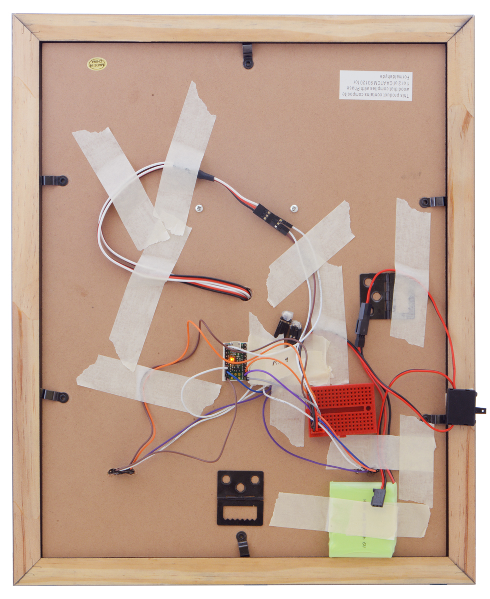
I also swapped the Maestro out for an A-Star 32U4 micro, so I could communicate with the sensors through I²C. Due to switching to the A-star micro, I added one of our small solderless breadboards to help distribute power and a servo Y splitter cable since both sub-micro servos can use the same signal. I also added a power switch and used some of our premium jumper wires to make connections. You can see all the electronics taped to the back of the picture frame in the picture below.
|
|

Related products


RC crawling skeleton

Our Halloween sale is still going strong! Visit the sale page for more information, and if you are in need of some inspiration, check out our Halloween-tagged blog posts for some sample projects, like this simple RC crawling skeleton that I made:
 |
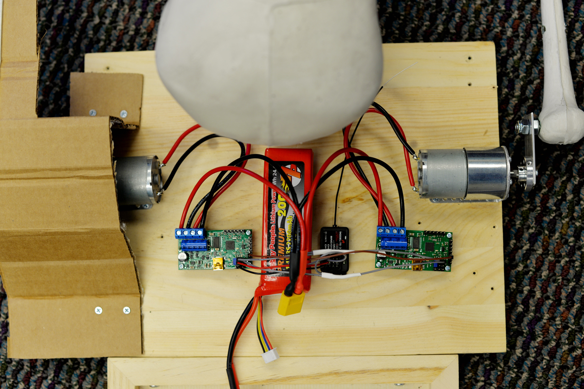
The setup for this project is pretty straightforward: a hobby RC transmitter sends signals through its receiver to a pair of Simple Motor Controllers, which each control a 37D mm gearmotor. The motors mount to a wooden base with a pair of L-brackets and connect to skeleton arms via universal aluminum mounting hubs and a short length of aluminum plating. The offset created by the aluminum plating causes the skeleton to move in a way that makes it look like it is slowly inching towards its next victim!
 |
A 3S LiPo provides power to the system through a pair of XT60 connectors, and the RC connections are made through some spliced female-female premium jumper wires. A black T-shirt covers up the electronics and a pair of cardboard “shoulder pads” help ensure the tee does not get tangled up in the rotation of the arm-bones.
|
|

In practice, the crawling skeleton is more amusing than scary: it crawls really slowly and the sound of the motors turning is too industrial/mechanical to haunt anyone’s dreams. The sound is, however, loud enough to startle any unsuspecting friends!
Related products


SK9822 LED jack-o-lantern

To kick off our 2018 mini-series of spooky Halloween projects, I’ll go over how I fixed and modified my family’s broken light-up jack-o-lantern, but first I want to remind you that our Halloween sale is still going on. Visit the sale page for more information, and if you are in need of some inspiration, check out our Halloween-tagged blog posts for some sample projects. Now, on to the jack-o-lantern…
 |
The lantern suffered from a couple of burnt out incandescent bulbs and an unreliable power switch. The switch had a poor mechanical connection somewhere, which meant that in addition to sliding it into the “on” position, the case had to be pressed/squeezed in just the right spot to connect power. I absolutely needed to replace the switch, but in addition, this was a good time to upgrade from a bland set of incandescent lights to a more customizable lighting solution by adding some individually addressable RGB LEDs.
I wanted to preserve the battery-powered functionality of the lantern, and since it is powered by 4 C batteries, it has a supply voltage that could be anywhere between about 4V and 6V. The SK9822 LED strips that I wanted to use run on 5V, so I would need some kind of regulator to power them, as well as a microcontroller to send them control signals. Fortunately, our A-Star Mini microcontrollers have onboard regulators that allow them to work with a wide operating range of voltages, and provide ample current that can be used for other devices in the system, like the SK9822. In particular, the A-Star Mini LV was a good fit for a system like this with a voltage that started above 5V and could drop below it as the batteries were drained. (That A-Star’s regulator can also provide about 1A of current!)
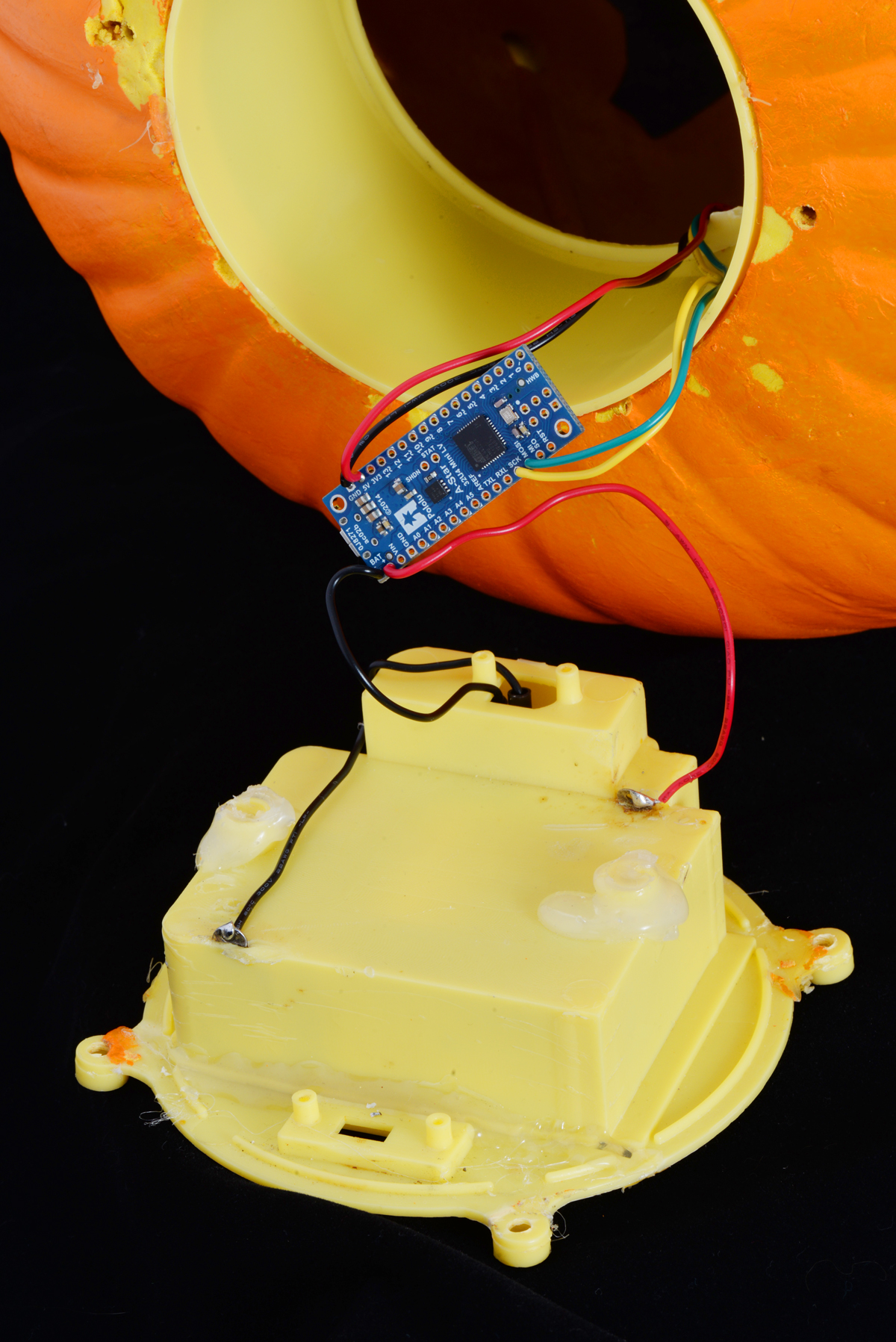 |
The A-Star mini LV and its connections. |
|---|
Starting the upgrade was pretty straightforward: remove all of the old hardware (the mess of old rusty wiring, the incandescent bulbs, and the switch), and solder in the A-Star to the battery holder terminals. From there, I soldered in a rocker switch that was much more satisfying to flip on and off than the older nonworking slide switch. Finally, I soldered up the four connections to the LED strip.
 |
The SK9822 LED strip segment taped to the outside of the plastic holder piece, as seen from the back of the jack-o-lantern. |
|---|
The strip itself only used 4 LEDs, since the lantern illuminates well and I didn’t want to unnecessarily consume lots of power (especially because the lantern was battery powered). The 4 piece segment was cut from one of the low density 30 LEDs per meter strips. The lower density meant that the LEDs were spaced out farther apart, which was useful to spread the LEDs across the plastic tube on the inside of the lantern and more evenly distribute the light. Our LED strip library made it easy to get started programming!
Another benefit of this hardware upgrade is the ability to reprogram the lighting display to whatever I want. Also, since the LED strips use so few IO pins, the decoration is in a good state to add additional electronics (like a proximity sensor or MP3 trigger)!
Related products


Polo-BOO! Halloween Sale
Looking to make an awesome Halloween costume or impressive yard display? Well, we want to help, so we’re having a sale through Wednesday, October 24 on hundreds of items you can use to make things that will impress or terrify your friends and neighbors! Visit the sale page for more information, and if you are in need of some inspiration, check out our Halloween-tagged blog posts for some sample projects.
By the way, we’d love to see more about the amazing things you all are building with our products, so please don’t hesitate to share them with us!
New product: Mounting Bracket for Standard-Size Servos
We now have a new mounting bracket available, this time designed for standard-size servos. Servos are very versatile and often make for an easy way to add precise motion to your project, but they can sometimes be difficult to mount due to their shape and the orientation of their intended mounting holes. Our new Mounting Bracket for Standard-Size Servos aims to solve that problem.
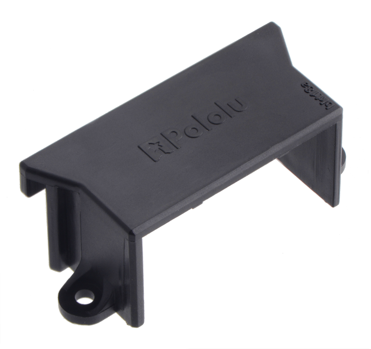 |
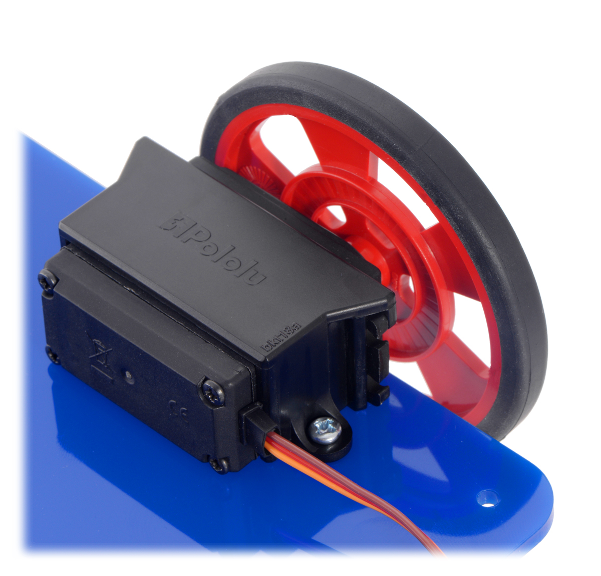
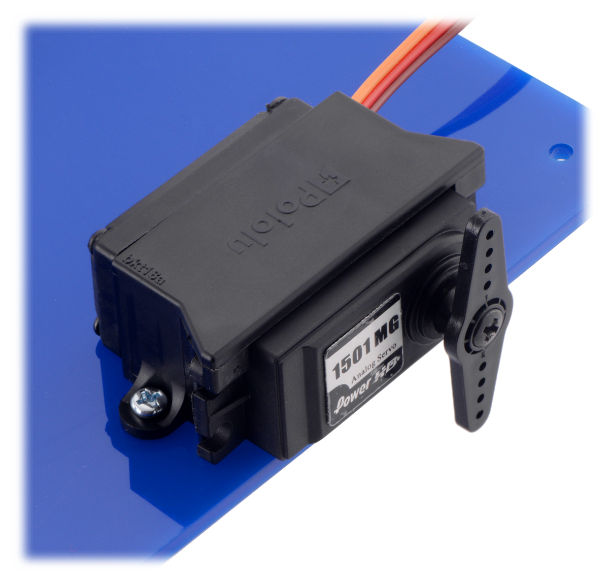
Instead of using the servo’s intended mounting holes, this bracket clasps around the servo, capturing its mounting tabs and providing an easy way to mount a servo on its side. The mounting holes on the bracket are intended for use with M3 or #4 screws (sold separately).
|
|
As with the Romi Expansion Plate we just released, this bracket was originally designed as part of our Robot Arm Kit for Romi.
Related products

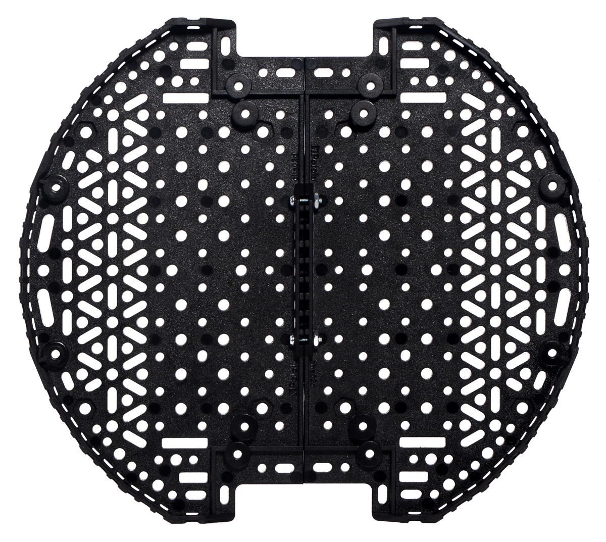
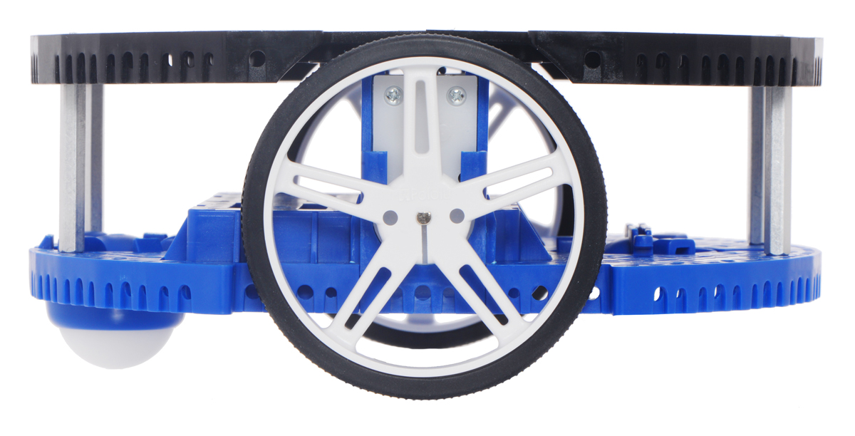
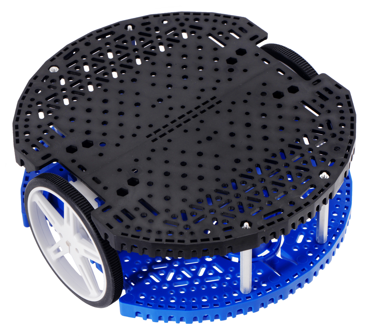
New product: Romi Chassis Expansion Plate

The Romi Chassis Expansion Plate is now available and is a great way to add even more space to the Romi. It is designed to function as a modular expansion option for the Romi. In fact, if you have been following our new product announcements, you might have already seen this plate as part of the Robot Arm Kit for Romi. The expansion plate is a half circle with the same diameter as the Romi base plate, and it can be installed over either the front or rear half of the Romi chassis. Abundant mounting holes and slots cover the plate, matching the pattern used on the Romi chassis base plate and supporting various sizes of screws.
|
|


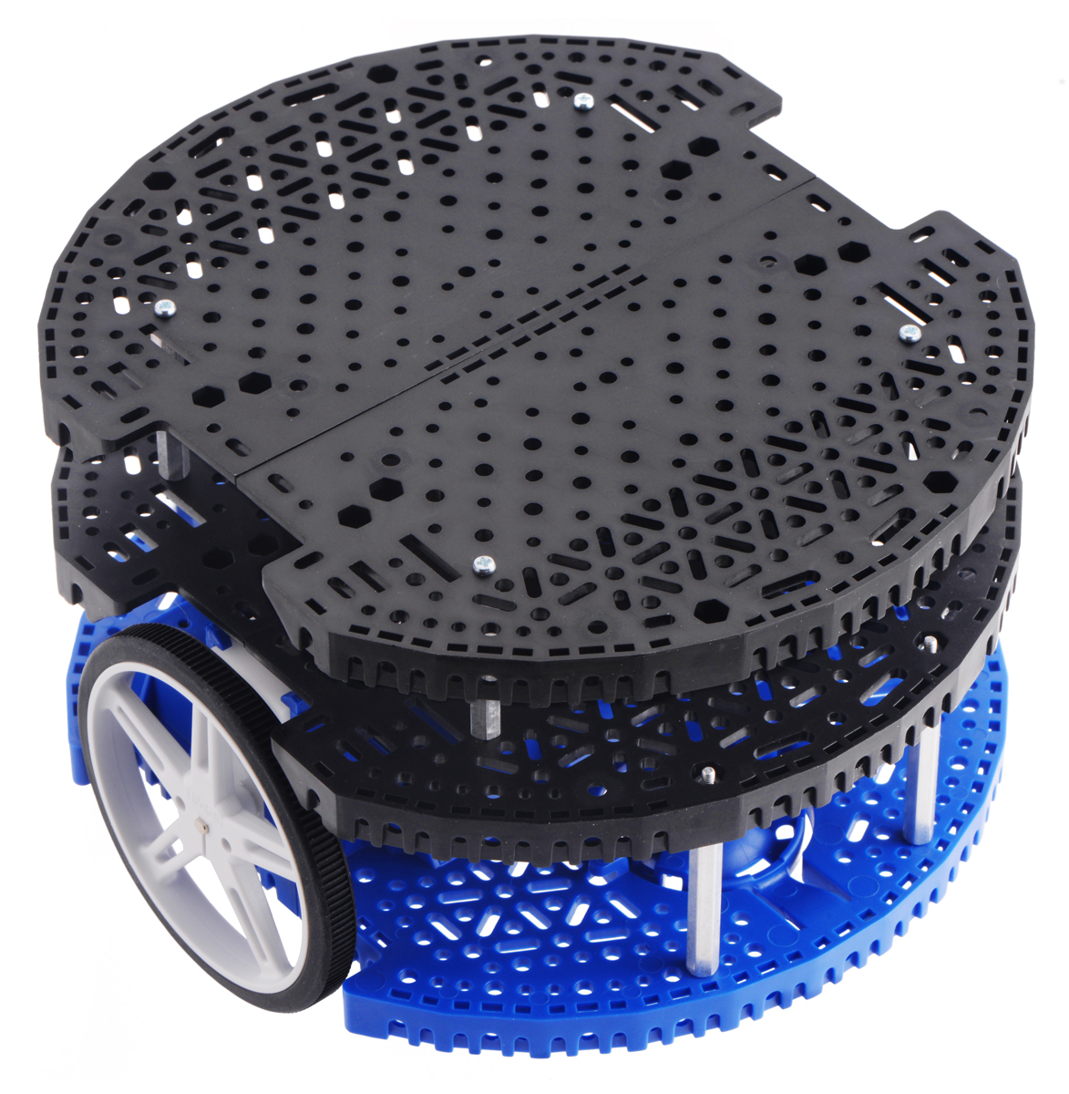
You can combine two plates to make a full-sized platform.
|
|
|
It is also possible to stack multiple expansion plates for even more versatility.
 |
Continuing with the special introductory discounts for all of our new products this year, the first 100 customers who use coupon code ROMIEXPINTRO can get up to 3 Romi Chassis Expansion Plates for just $3.33 each!
Related products

New-ish product roundup: 24 more QTR arrays, MP6500 carriers with soldered headers, and a pressure sensor
We’ve been hard at work over the past week putting up lots of new (but perhaps familiar-seeming) products. Here’s a quick recap:
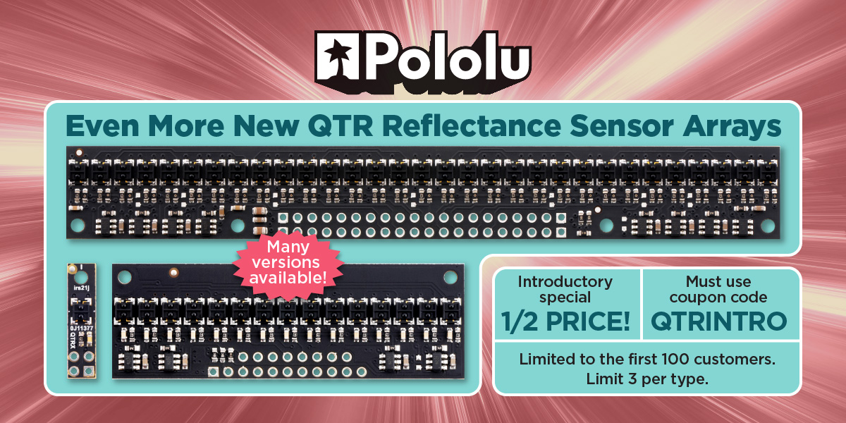
24 new QTR reflectance sensor arrays
Our rapidly growing selection of new QTR sensors now includes high-density (HD) versions with 3, 6, and 9 channels, and medium-density (MD) versions with 2, 3, and 5 channels.
|
|
|
|||
|
|
|


Each of these is available with two sensor options—traditional QTR and high-performance, low-current QTRX—and with analog or digital (RC) outputs, making 24 new products in all. Check out the QTR reflectance sensor category to see our full selection, which now stands at 68 varieties, and don’t forget to use our QTR introductory promotion to get 50% off any of these new sensors! (Limited to the first 100 customers who use coupon code QTRINTRO, limit 3 per item per customer.)

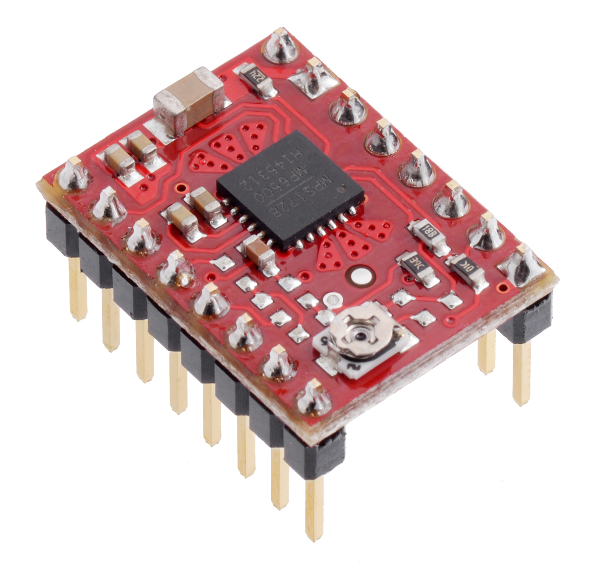
MP6500 stepper motor driver carriers with soldered header pins
 |
 |
We have received a number of requests to make the MP6500 stepper motor driver carriers we released earlier this year available with the header pins already soldered, so here they are! These carriers are available in two versions, one with the current limit set by a potentiometer, and one that allows for dynamic current limit control through a pair of digital inputs, and both are now available with soldered header pins:
- MP6500 Stepper Motor Driver Carrier, Potentiometer Current Control (Header Pins Soldered)
- MP6500 Stepper Motor Driver Carrier, Digital Current Control (Header Pins Soldered)
For a more detailed introduction to these drivers, see our original MP6500 carrier product announcement.
LPS25HB pressure/altitude sensor carrier
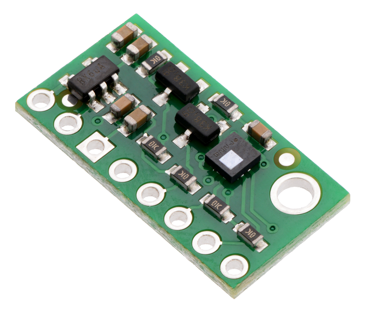
This is a minor update to our existing LPS25H pressure sensor carrier, which is now on clearance. The new version uses the same PCB as the original, hence the “©2014” on the silkscreen. and replaces the LPS25H with the newer LPS25HB, a drop-in replacement with the same register map and performance. Most people shouldn’t notice any difference using the new version compared to the old one, though ST says in their LPS25H upgrade guide (200k pdf) that the LPS25HB has better moisture resistance and reliability. That said, please keep in mind that we have not characterized the moisture resistance of the rest of the carrier, and moisture is generally something we recommend you keep away from all of our electronics.
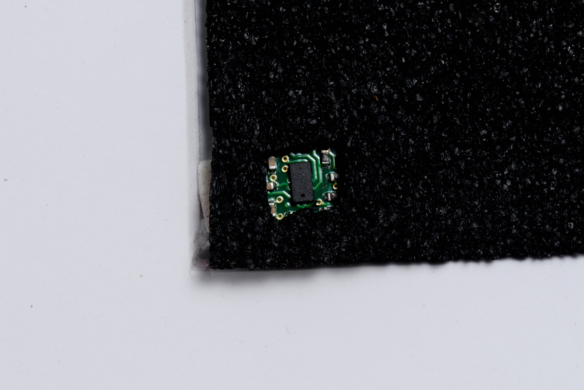
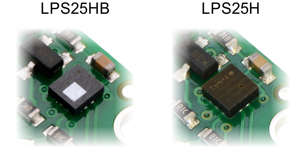
Visually, the LPS25HB is easy to distinguish from the LPS25H as the former has a shiny silver square patch on the package while the latter has a more noticeable hole:
 |
We have already started making our AltIMU-10 v4 and AltIMU-10 v5 IMUs with the LPS25HB, and we did so without using new product numbers or updating the pictures or descriptions because this change should not affect those products in any meaningful way (we have a new product number for the updated basic carrier since the specific sensor on there is pretty much the whole point of the product).
On a related note, we still have a lot of the even older LPS331AP pressure sensors/digital barometers left, so we have put the LPS331AP carriers on even more clearancy clearance!
Related products


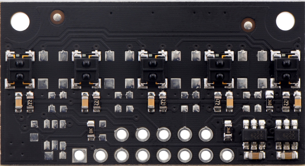
New products: 5-channel QTR HD reflectance sensor arrays
 |
QTRX-HD-05RC Reflectance Sensor Array, front and back views. |
|---|
We now have five-sensor versions of our new high-density QTR reflectance sensor arrays. Like the versions already released, these new modules are available in analog and RC configurations and with two different sensor types, so this post covers four new products:
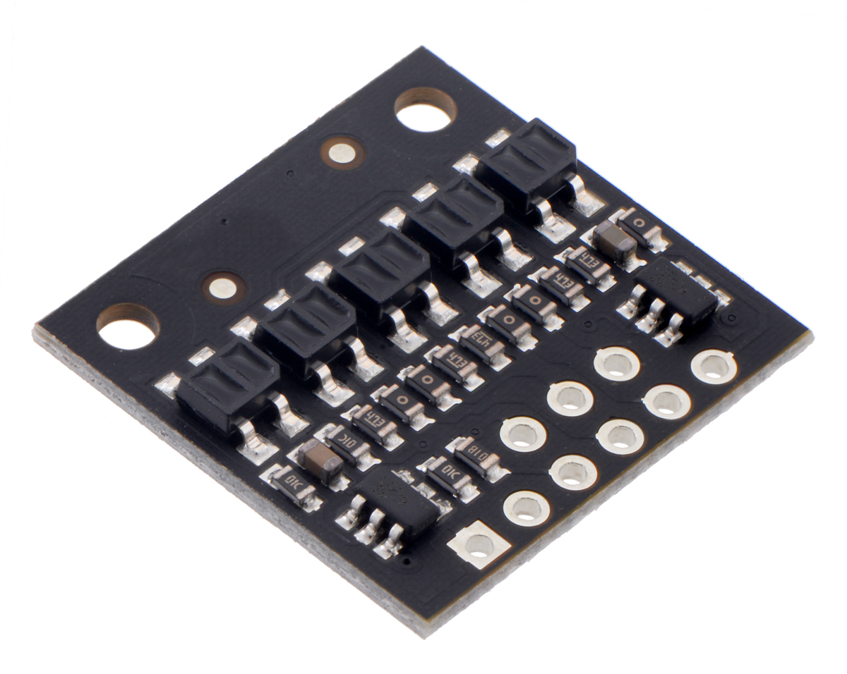 |
QTR-HD-05A Reflectance Sensor Array. |
|---|
- QTR-HD-05RC Reflectance Sensor Array
- QTR-HD-05A Reflectance Sensor Array
- QTRX-HD-05RC Reflectance Sensor Array
- QTRX-HD-05A Reflectance Sensor Array
(Medium-density versions with 3 sensors on an 8 mm pitch will be available soon.)
We expect these to be the smallest arrays that still offer independent control of the odd and even emitters, which gives you extra options for detecting light reflected at various angles. For more information on our new QTR sensor family, you can see some of our previous blog post about the versions we have already released:
- New products: 1- and 31-channel QTR HD reflectance sensor arrays
- New products: more new QTR HD sensor arrays by student engineering interns
- New products: QTR HD sensor arrays by student engineering interns
- New product: high-density QTR reflectance sensor arrays
Don’t forget to get in on our QTR introductory promotion! Be one of the first 100 customers to use coupon code QTRINTRO and get any of these new sensors at half price! (Limit 3 per item per customer.)
Related products


Labor Day weekend sale

We are having a Labor Day sale all weekend long with site-wide discounts of up to 25%! Check out the sale page for more information. Please note that we will be closed Monday, so orders placed after 2 PM Pacific Time today (Friday, August 31) will be shipped on Tuesday, September 4.


Home | Forum | Blog | Support | Ordering Information | Lists | Distributors | BIG Order Form | About | Contact
© 2001–2026 Pololu Corporation


