Pololu Blog » Posts tagged “new products” »
Posts tagged “new products” (Page 12)
You are currently viewing a selection of posts from the Pololu Blog. You can also view all the posts.
Popular tags: community projects new products raspberry pi arduino more…
New products: Jrk G2 USB Motor Controllers with Feedback
After many months or years of work (depending on how you look at it), I am happy to introduce our newest motor controllers, the Jrk G2 USB Motor Controllers with Feedback, which we are releasing today in four power variants:
 Jrk G2 18v19 |
 Jrk G2 24v13 |
 Jrk G2 18v27 |
 Jrk G2 24v21 |
|
|---|---|---|---|---|
| Recommended max operating voltage: |
24 V(1) | 34 V(2) | 24 V(1) | 34 V(2) |
| Max nominal battery voltage: |
18 V | 28 V | 18 V | 28 V |
| Max continuous current (no additional cooling): |
19 A | 13 A | 27 A | 21 A |
| Dimensions: | 1.4″ × 1.2″ | 1.7″ × 1.2″ | ||
1 30 V absolute max.
2 40 V absolute max.
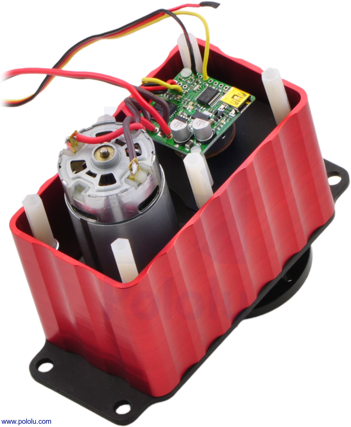 |
The main purpose of the Jrk G2 family is to enable feedback-based control of DC brushed motors, simplifying closed-loop control of things like the position of an actuator. An example that is probably familiar to most of us is the common hobby servo that has an output shaft that can rotate to various positions as commanded over a simple interface. The Jrk motor controllers can be used for giant versions of those servos, and they can also be used in many other systems as long as you can somehow get feedback in the form of an analog voltage or a frequency. Analog voltage feedback is often easy to get from potentiometers that can serve as angle or position sensors.
The frequency feedback feature is handy for maintaining a speed of a motor independent of your supply voltage and motor load. You might use that kind of feature to run a treadmill at some set speed independent of the weight of the lab rats on it or to stir some jar of goop at a constant rate as the goop gradually thickens. With mobile robot applications, it can be handy to have a motor controller that will make your wheel go at the speed you set independent of whether the robot is on a hard floor or a carpet. (The Jrks do not support quadrature encoders, but you can use one channel of a quadrature encoder as the tachometer for the Jrk. In some applications, keeping track of absolute position is not necessary, or the quadrature encoder can be monitored directly by a main controller that could still benefit from the closed-loop speed control being taken care of by the motor controller.)
To control a wide range of motors in a variety of applications, it’s important to be able to configure a lot of parameters, which makes the Jrk’s USB connection and free configuration utility software extremely important. Even if you ultimately want to use your Jrk in a radio control installation or command it over I²C from your favorite embedded controller, it’s very convenient to be able to set everything up from your computer.
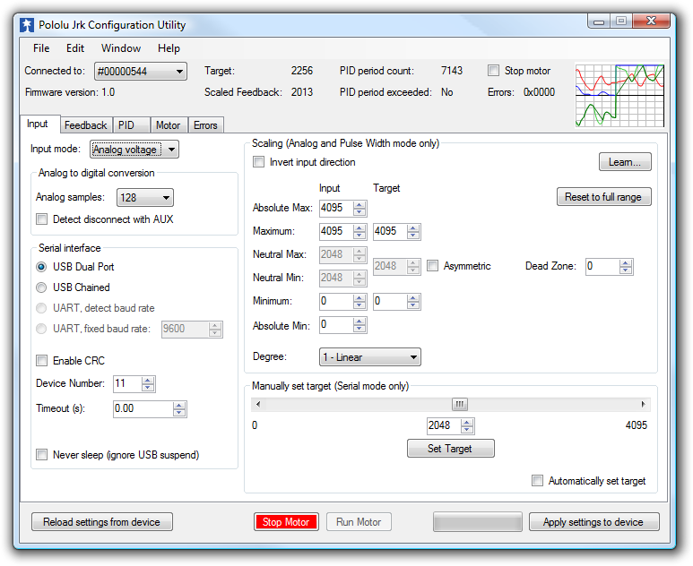 |
That screenshot is actually of the utility for the original Jrks, which we released almost 9 years ago (I announced those on the forum because we did not have this blog back then). You might notice on some older web pages that we referred to the original Jrks as our second-generation feedback controllers. The really original ancestor to today’s new motor controllers is this product we called simply Pololu 3A Motor Controller with Feedback, which we released at the beginning of 2005. Here are a picture and block diagram of that controller:
|
|
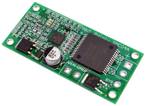 |
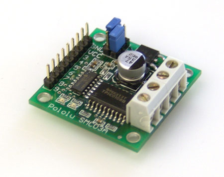
Candice and I were probably still running Pololu out of our house back when we started work on that controller, and it’s probably the last product of ours for which Candice wrote some of the firmware. That controller led to the development of a larger, customized controller (similar to our SMC04 High-Power Motor Controller with Feedback) and an even higher-power version that was used on control cables of large autonomous parachutes for the military.
Back to the new Jrk G2 family: these new controllers are in many ways a refinement of the original Jrks, which have been used all over the world in applications from animatronic displays to motion simulators and even full-sized airplanes. The most noticeable improvement on the four Jrk G2 controllers we are releasing today is the increased power available from their discrete MOSFET H-bridges. The G2 high-power motor driver design is part of the reason for the “G2” in the new Jrk family name, though we plan on releasing lower-power, smaller Jrk G2 products later this year. The new driver technology, along with going to double-sided PCB assembly and four-layer PCBs, allowed us to make much higher-power controllers that are smaller than the old Jrk 12v12, which used to be our highest-power version.
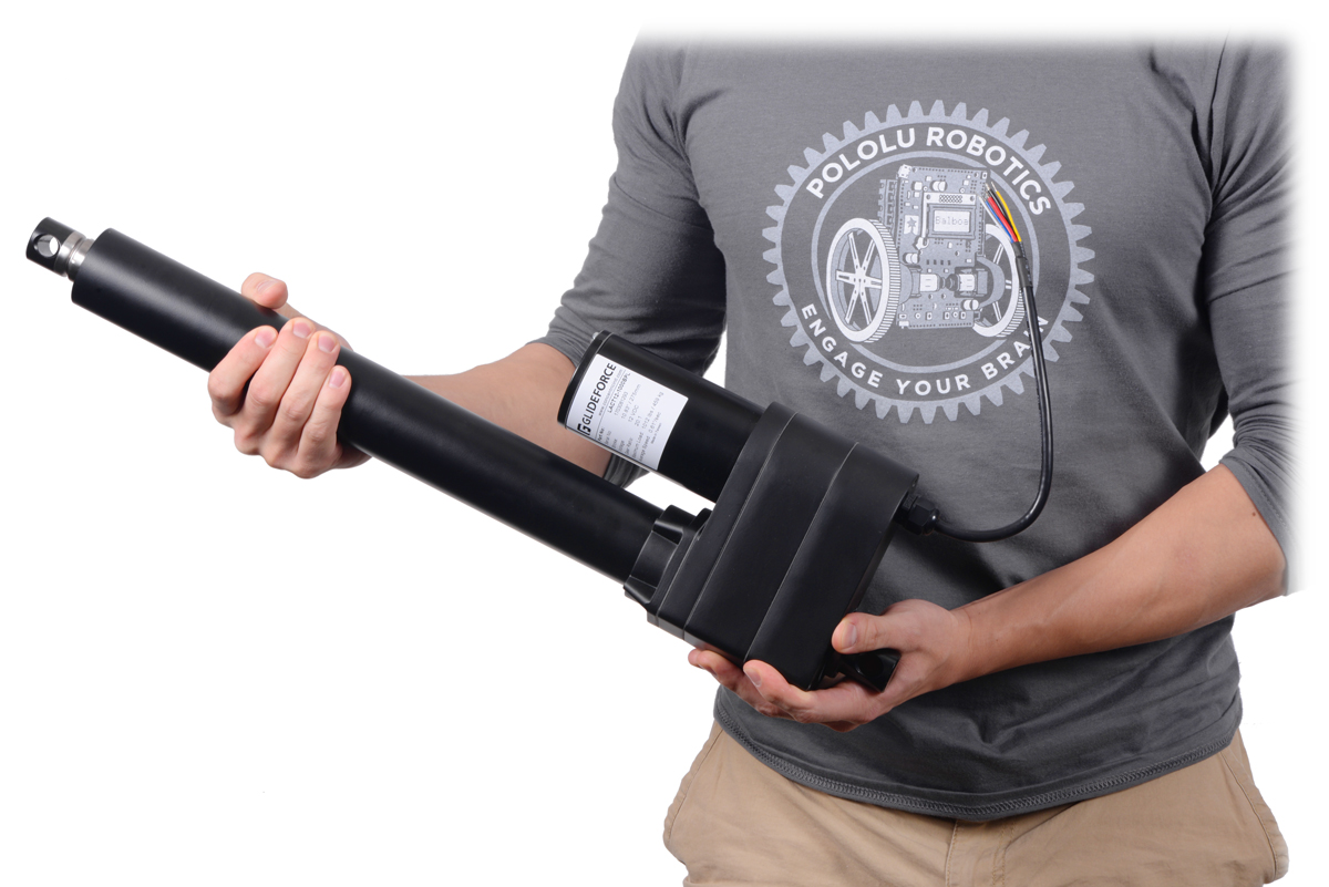
The Jrk G2 24v13 and 24v21 in particular open up new application opportunities because they can operate off of 24 V power rails, making them appropriate for huge linear actuators (note that we only carry 12 V versions right now, partly because we did not have controllers that we could recommend for 24 V use). It’s exciting that these tiny boards can control such huge actuators, and the size difference is so big it’s difficult to convey in a picture:
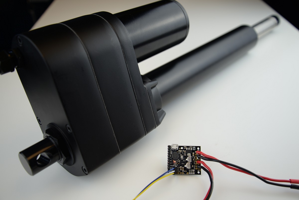 |
The size difference makes it difficult to get a Jrk G2 24v13 and an industrial-duty linear actuator in the same picture. |
|---|
Other features new to the G2 Jrks are an I²C interface option and an improved tachometer/frequency feedback mode that now offers pulse width measuring rather than only frequency counting to allow for better control of low-speed motors with lower-resolution encoders or tachometers. Here is a summary of the main features of the Jrk G2 motor controllers:
- Easy open-loop or closed-loop control of one brushed DC motor
- A variety of control interfaces:
- USB for direct connection to a computer
- TTL serial operating at 5 V for use with a microcontroller
- I²C for use with a microcontroller
- RC hobby servo pulses for use in an RC system
- Analog voltage for use with a potentiometer or analog joystick
- Feedback options:
- Analog voltage (0 V to 5 V), for making a closed-loop servo system
- Frequency pulse counting (for higher-frequency feedback) or pulse timing (for lower-frequency feedback), for closed-loop speed control
- None, for open-loop speed control
- Note: the Jrk does not support using quadrature encoders for position control
- Ultrasonic 20 kHz PWM for quieter operation (can be configured to use 5 kHz instead)
- Simple configuration and calibration over USB with free configuration software utility
- Configurable parameters include:
- PID period and PID constants (feedback tuning parameters)
- Maximum current
- Maximum duty cycle
- Maximum acceleration and deceleration
- Error response
- Input calibration (learning) for analog and RC control
- Optional CRC error detection eliminates communication errors caused by noise or software faults
- Reversed-power protection
- Field-upgradeable firmware
- Optional feedback potentiometer disconnect detection
As with all of our new product releases this year, we are offering an extra introductory discount: the first 100 customers to use coupon code JRKG2INTRO can get 40% off up to three units. (Click to add the coupon code to your cart.)
Related products


New products: Dual MAX14870 Motor Drivers for Arduino and Raspberry Pi
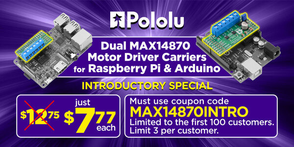
For my birthday, I am excited to share two new products to help get your projects moving: dual motor driver boards for Arduino and for Raspberry Pi based on Maxim MAX14870 drivers, which on these boards (without additional cooling) can power motors with a continuous 1.7 A (2.5 A peak) from a voltage source anywhere from 4.5 V to 36 V. This makes the driver ideal for powering a wide range of motors including our high power micro metal gearmotors, and our 12 V 20D mm metal gearmotors. We like the MAX14870 so much that already we make a single driver carrier for it, and we use it on our A-Star 32U4 Robot Controller SV. These new boards make it easy to control two motors using the MAX14870 with an Arduino or Raspberry Pi.
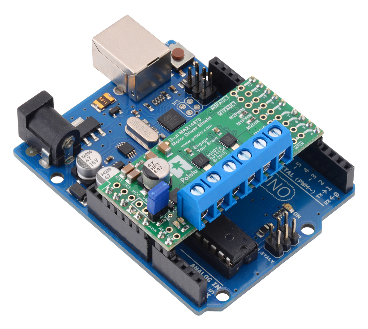 |
The Dual MAX14870 Motor Driver Shield for Arduino is designed to plug directly into an Arduino or another microcontroller board with the Arduino form factor. It connects the Arduino I/O pins to the two-pin speed/direction interfaces as well as the fault output pins, and our open-source library is available to help you get started. The shield can be set up to power your Arduino device from your motor power supply, which is especially helpful if you are using an Arduino or compatible device with an operating voltage similar to that of the MAX14870, such as our A-Star 32U4 Prime SV. Additionally, the board can be customized to use the advanced features of the MAX14870 drivers or change the pin mappings.
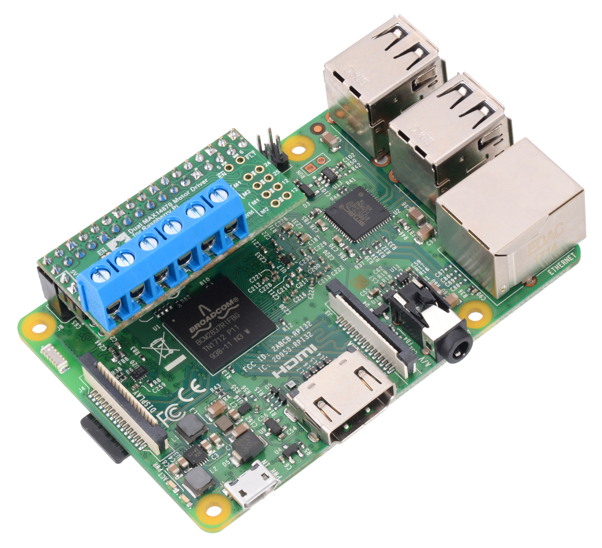
The Dual MAX14870 Motor Driver for Raspberry Pi has many of the same features as the Arduino version, but it is designed to plug into the GPIO header on a compatible Raspberry Pi (Model B+ or newer), including the Pi 3 Model B and Model A+. We provide an open-source Python library to make it easy to interface with the board. This board also has a location to connect a step-down 5 V regulator to power the Raspberry Pi from your motor’s power supply.
|
|

I am really excited about these boards because the Raspberry Pi expansion board is the first PCB I ever designed, and the Arduino shield was designed by my friend David S. Both of us are engineering students at the University of Nevada, Las Vegas who work at Pololu to complement our studies. It has been a great experience for us to learn how to design these products from the development engineers here at Pololu. Plus, getting to share these products for the first time with you is a fun way to celebrate my birthday!
As usual for our new product releases this year, we’re offering an extra introductory discount: the first 100 customers to use coupon code MAX14870INTRO can get any mix of up to 3 of these boards for $7.77 each. (Click to add the coupon code to your cart .) Note that this introductory offer applies only to the units without connectors soldered in.
Related products


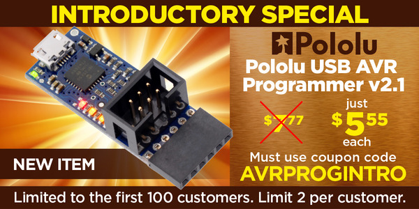
New product: Pololu USB AVR Programmer v2.1
Our new programmer, the Pololu USB AVR Programmer v2.1, was supposed to be a minor update to our existing programmer, coming right after the A-Star 328PB Micro that we released last month, with the main point of excitement being the Las Vegas-inspired $7.77 price. But as we were testing the combination of the programmer with the A-Star, we were getting brown-out resets on the programmer when it powered the A-Star. The relevant part of the circuit was just a P-channel MOSFET that connected the programmer’s own logic voltage (which we call VDD) to the VCC pin of the ISP connector:
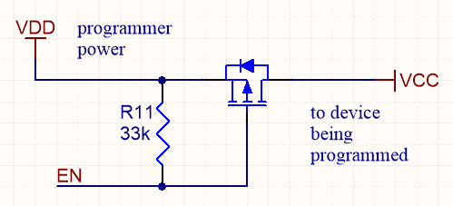 |
MOSFET-based target VCC power control used on Pololu USB AVR Programmer v2. |
|---|
The problem was caused by the MOSFET turning on too well (quickly and with low resistance), causing the logic voltage on the programmer to drop if the VCC of the target device had more than a few µF of discharged capacitance on it. The bigger the capacitance on VCC, the bigger the voltage drop on VDD, until eventually the drop was big enough to trigger the brown-out reset protection on the programmer’s microcontroller. We tried various firmware tricks with our existing hardware, such as turning on the MOSFET for very short pulses to gradually charge up the target device’s VCC capacitance, but none of them worked reliably enough. So in the end, we decided to redo our PCB and put in a dedicated high-side power switch with a controlled slew rate. The new programmer can now power target boards with up to about 33 µF on their logic supplies.
These are the two other improvements we made to the new v2.1 programmer over the older v2 programmer:
 |
- Plugging a v2 programmer into a 3pi robot could cause one of the motors to briefly run at full speed because the programmer’s circuitry for measuring VCC could inadvertently pull up one of the 3pi’s programming pins (which doubles as a motor driver input) before the GND connection was established. The v2.1 programmer has improved circuitry for measuring VCC which limits the duty cycle of this effect to about 0.2%, so the motor won’t move (but it might make a 25 Hz clicking sound).
- The v2 programmer would typically brown-out if a 5 V signal was applied to its RST pin while it was operating at 3.3 V. The v2.1 programmer does not have this problem.
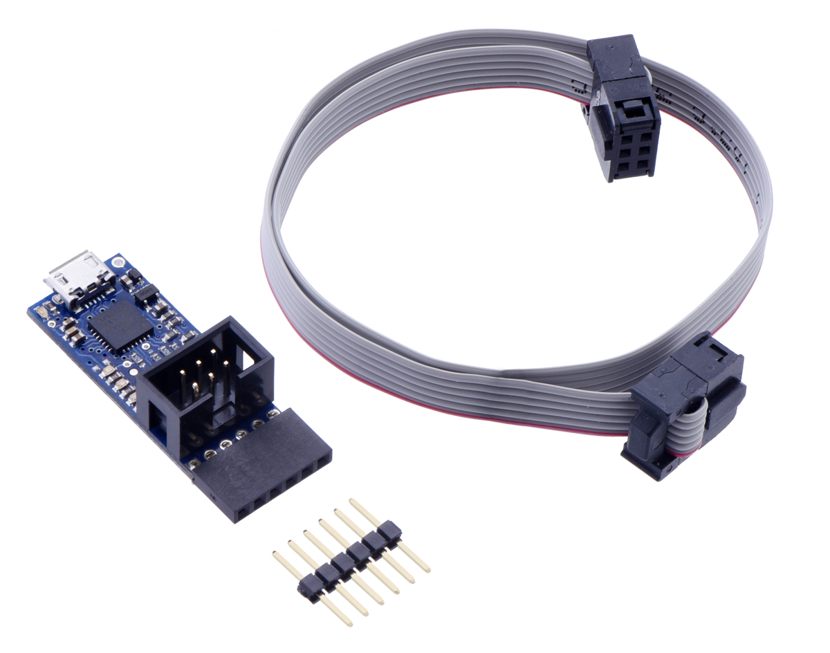
The v2.1 programmer is otherwise identical to the v2 programmer, which means it’s a USB AVR microcontroller programmer that can program targets at 3.3 V and 5 V and offers an extra UART-type TTL serial port (like the popular FTDI USB-to-serial adapters) that can be super handy for debugging, bootloading, or even general connection of your project to a USB port.
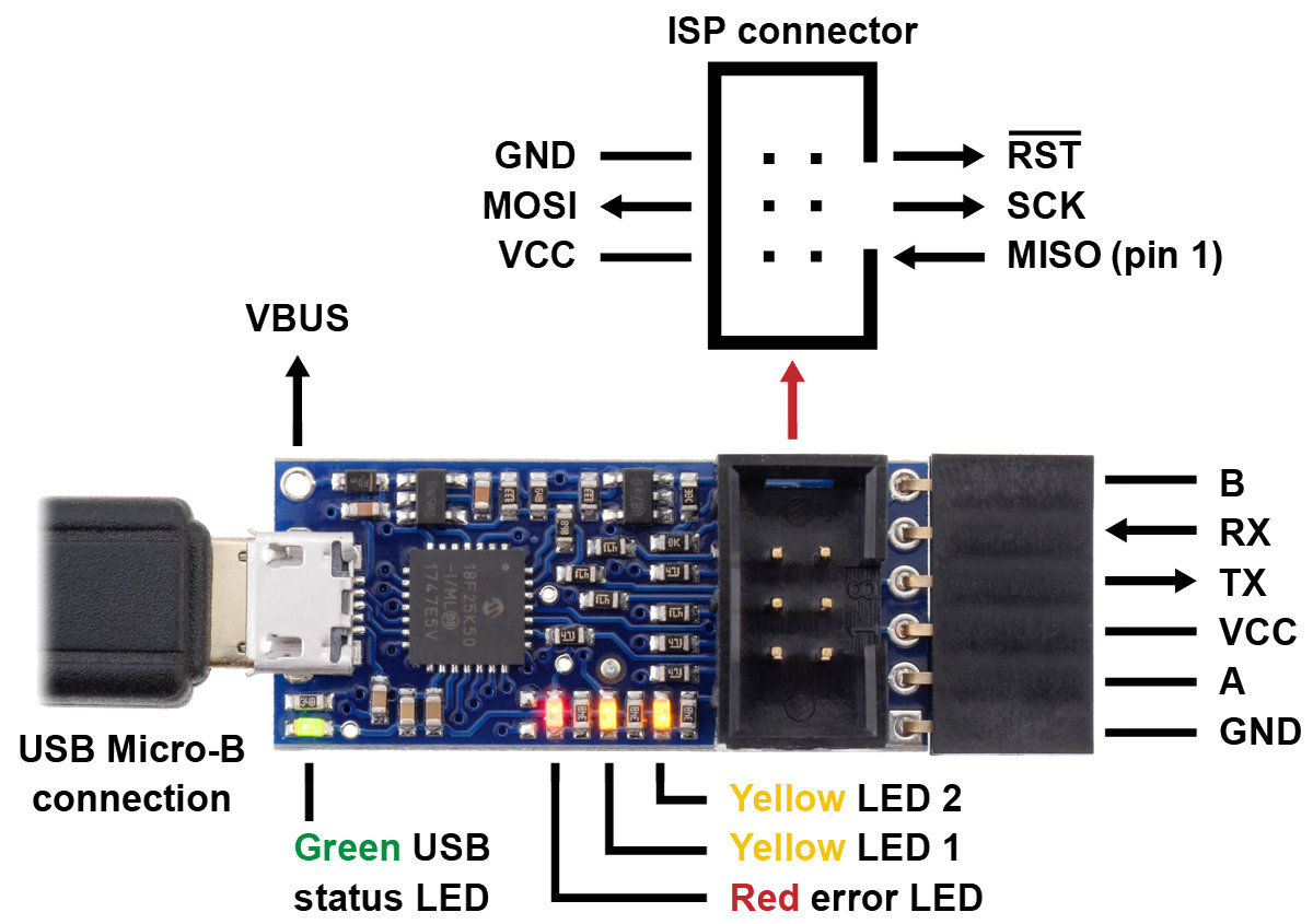 |
Pololu USB AVR Programmer v2.1, labeled top view. |
|---|
The v2 programmer was already a good deal at under $12, but at $7.77, and with free shipping in the USA, we hope to make AVR development extremely accessible. The manufacturing improvements and other cost reduction initiatives I have been blogging about this year help us make this offer without losing money on it, but I am not expecting to be making money directly off of the programmers, either. My goal is to give you the best value in a basic tool you will use over and over as you build your own projects, with the hope that that will help you keep Pololu in mind the next time you need some electronics or robotics parts.
And, as usual for our new product releases this year, we’re offering an extra introductory discount: the first 100 customers to use coupon code AVRPROGINTRO get that already great $7.77 price dropped to $5.55 (limit 2 per customer). (Click to add the coupon code to your cart.)
Related products

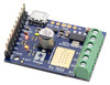
New products: RoboClaw Solo 30A and 60A Motor Controllers
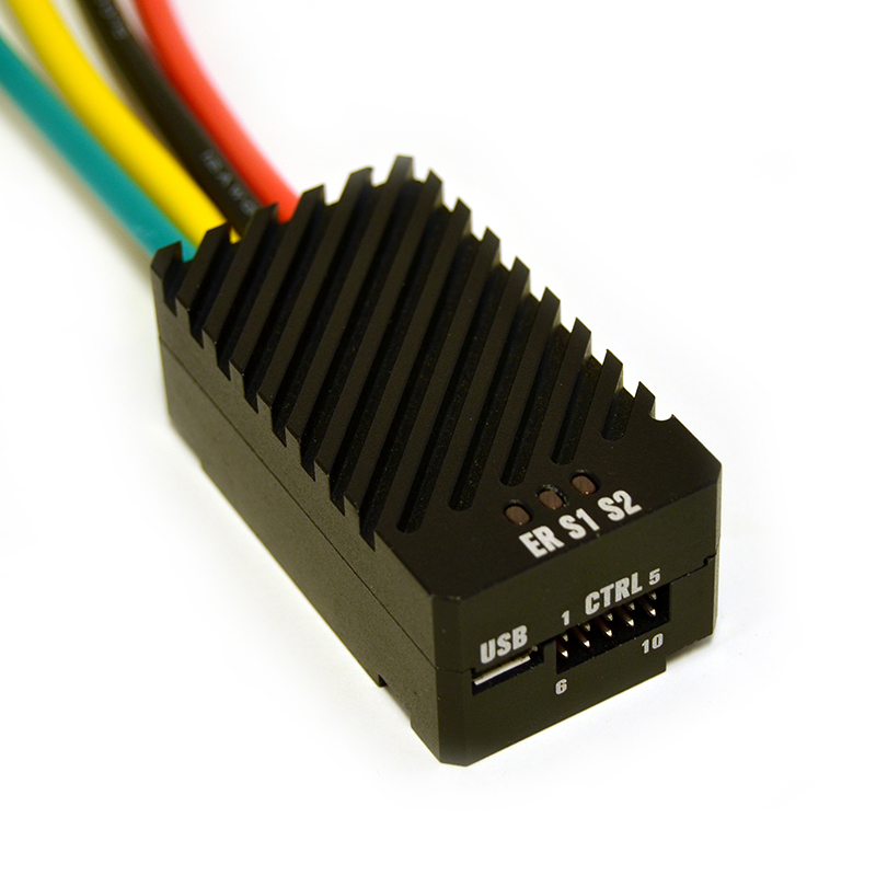 |
We are now carrying Ion Motion Control’s line of single-channel RoboClaws, the Solo 30A and Solo 60A. These versatile, high-power motor controllers have nearly all the same features and performance capabilities as their dual-channel 2×30A and 2×60A counterparts, just with one fewer motor channel. Just like the rest of the RoboClaw family, the Solos support a variety of interfaces, including USB serial, TTL serial, RC hobby servo pulses, and analog voltages, and integrated quadrature decoders enable closed-loop position or velocity control.
Unlike our selection of dual-channel RoboClaws, the Solos also feature a rugged, all-metal case that protects the driver while simultaneously serving as a heat sink, and they have four 12 AWG unterminated leads for supplying power and connecting a motor.
The following table shows our full updated offering of RoboClaw motor controllers:
 Solo 30A |
Solo 60A |
 2x7A |
 2x15A |
2x30A |
2x45A ST 2x45A |
 2x60A |
|
|---|---|---|---|---|---|---|---|
| Motor channels: | 1 | 2 | |||||
| Operating voltage: | 6 V to 34 V | 6 V to 34 V | |||||
| Continuous output current: | 30 A | 60 A | 7.5 A | 15 A | 30 A | 45 A | 60 A |
| Peak output current: | 60 A | 120 A | 15 A | 30 A | 60 A | 60 A | 120 A |
| 5V BEC max current: | 1.2 A | 1.2 A (V5B or later) | 3 A | ||||
| Size | 60 × 32.5 × 23.5 mm | 48 × 42 × 17 mm | 74 × 52 × 17 mm | 100 × 86 × 25 mm | |||
| Weight: | 130 g | 18 g | 60 g | 295 g | |||
| Price: | $89.95 | $119.95 | $114.95 | $129.95 | $169.95 | $191.95 | $199.95 |
Related products

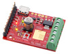
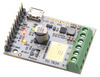
New product: Tic T500 USB Multi-Interface Stepper Motor Controller
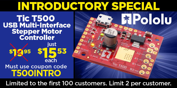
Our Tic stepper motor controllers are pretty awesome, and the new Tic T500 we released today should make stepper motors even more accessible for your next project. This latest version features a broad 4.5 V to 35 V operating range that covers everything from small 2-cell lithium battery packs up to 24 V batteries or power supplies while costing just $20 in single-piece quantities. This video gives you a quick overview of what the Tic stepper motor controllers offer:
The Tics make basic speed or position control of a stepper motor easy, with support for six high-level control interfaces:
- USB for direct connection to a computer
- TTL serial operating at 5 V for use with a microcontroller
- I²C for use with a microcontroller
- RC hobby servo pulses for use in an RC system
- Analog voltage for use with a potentiometer or analog joystick
- Quadrature encoder input for use with a rotary encoder dial, allowing full rotation without limits (not for position feedback)
The Tic T500 is available with connectors soldered in or without connectors soldered in. Here is a handy comparison chart with all three Tic stepper motor controllers:
 Tic T500 |
 Tic T834 |
 Tic T825 |
|
|---|---|---|---|
| Operating voltage range: | 4.5 V to 35 V(1) | 2.5 V to 10.8 V | 8.5 V to 45 V(1) |
| Max current per phase (no additional cooling): |
1.5 A | 1.5 A | 1.5 A |
| Microstep resolutions: | full half 1/4 1/8 |
full half 1/4 1/8 1/16 1/32 |
full half 1/4 1/8 1/16 1/32 |
| Automatic decay selection: |  |
||
| Price (connectors not soldered): | $32.95 | $42.95 | $42.95 |
| Price (connectors soldered): | $34.95 | $44.95 | $44.95 |
1 See product pages and user’s guide for operating voltage limitations.
Basically, the new T500 does not offer the finer microstep resolutions of the T834 and T825, and the T834 supports very low operating voltages while the T825 supports higher operating voltages.
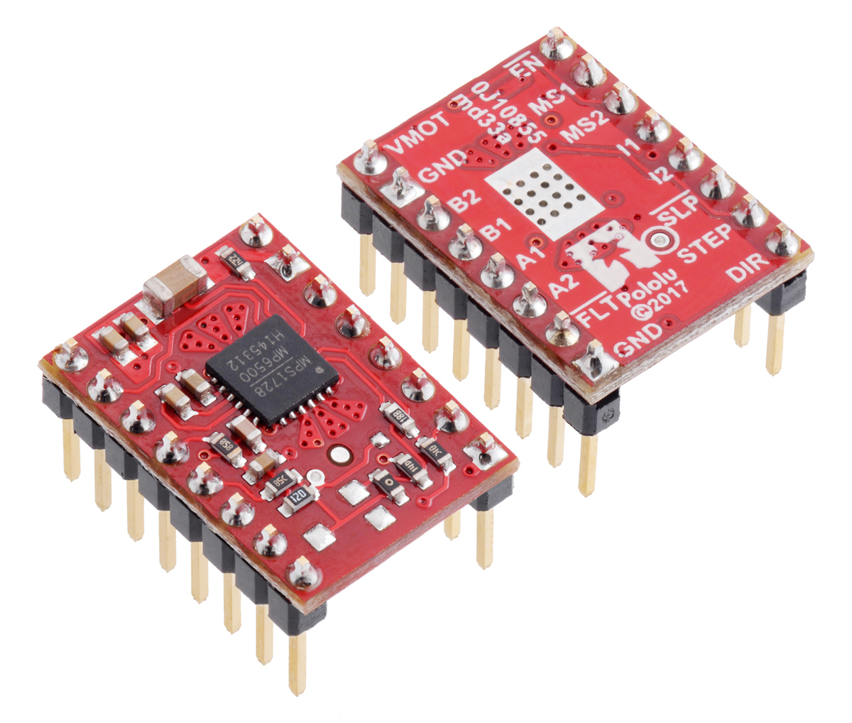
For those of you interested in more of the details of the stepper motor driver, the Tic T500 uses the new MP6500 from MPS, which we also offer on some low-cost MP6500 breakout boards with analog (small trimmer potentiometer) and digital (via PWM) current limit setting options.
In keeping with the tradition we started this year, we are offering an extra discount for the first customers, to help share in our celebration of releasing a new product. The first hundred customers to use coupon code T500INTRO can get up to two units for just $15.53! (Click to add the coupon code to your cart.) And we’ll even cover the shipping in the US! Note that this introductory offer applies only to the units without connectors soldered in.
Related products


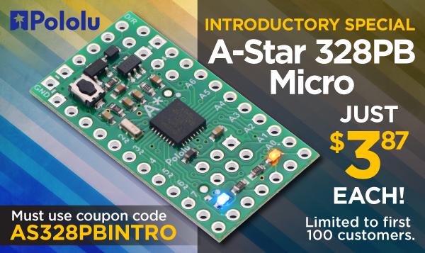
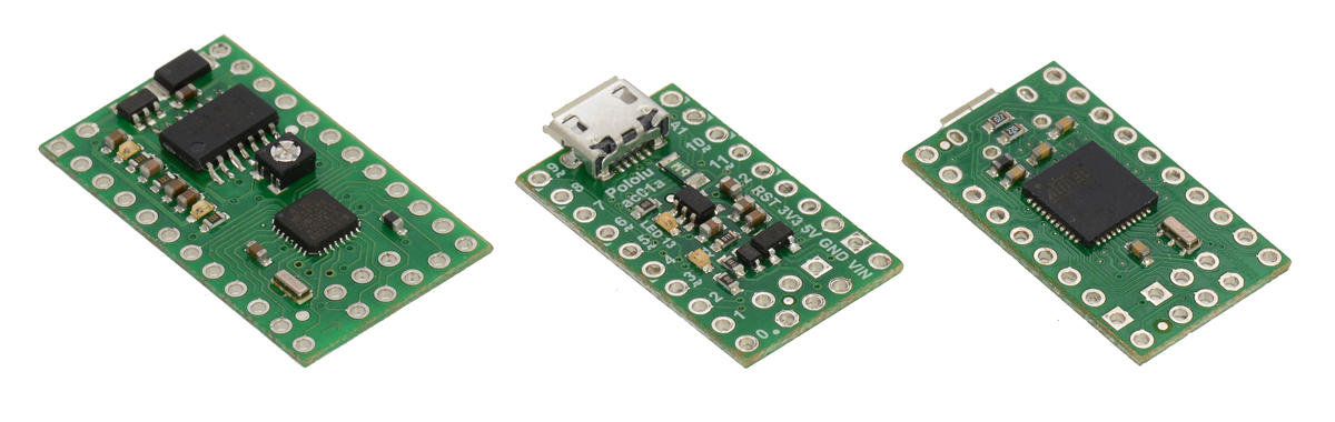
New product: A-Star 328PB Micro
Today we are releasing our newest A-Star programmable controller, the A-Star 328PB Micro. It is basically our version of the ubiquitous Arduino Pro Mini type products, but with the newer ATmega328PB microcontroller. The board itself is pretty straightforward (though the updated AVR is exciting), so the main thing I want to share in this post is our history with the Atmel ATmega328PB microcontrollers (this was before Microchip acquired Atmel) and how this product would not have existed without our lower-cost manufacturing initiative that I have been discussing.
We have been using the ATmega8, and then the ATmega48, ATmega168, and ATmega328P, since 2004 in many of our user-programmable products because of their versatility and excellent free compiler support (which also made Arduino possible). We first heard about the ATmega328PB in early 2014. The product kept being delayed, and I did not get a quote for them until October 2015. I ordered a reel right away; it arrived in March 2016. Over those two years, we put our AVR-related efforts into the ATmega32U4, releasing several A-Star 32U4 programmable controllers and using it on robots like the Zumo 32U4. The ATmega32U4 was a superior part with native USB and more I/O lines, making it a better fit for many of our applications. By the time we finally got the ATmega328PB parts, we had the A-Star 32U4 Micro available for just $12.75, making it less exciting to put effort into a lower-performance product that might end up costing almost the same amount.
 |
Original ATmega168-based Baby Orangutan robot controller from 2005 (left) next to A-Star 32U4 Micro boards. |
|---|
The new manufacturing equipment I ordered in the fall of 2017, along with the availability of our latest AVR programmer, brought attention back to the feasibility of a basic ATmega328PB carrier. I was hesitant to put effort into a product where we could not offer something substantially more compelling than what was already available. Despite the ATmega328PB being out in the wild for almost two years, it still had not really made it into many Arduino products, so I thought that perhaps we could offer something there. But more importantly, I wanted to see how low we could price it. I was aware of Arduino Pro Mini clones available on eBay and the AliExpress-type sites for under $3. Most official Arduino Pro Mini type products cost more like $10. For this project to be worthwhile, I wanted to get under $5.
It turns out we had to squeeze quite a bit just to get to the upper limit of that “under $5” goal, and so we are releasing this product at a unit retail price of $4.95. It’s not the under-$3 you can find for the absolute cheapest clones, but if you get the A-Star 328PB Micro from us, you are getting a well-supported, well-made product (each unit is 100% automatically visually inspected and 100% functionally tested) and supporting a company that is doing more than just copying products that are already out there.
It is my hope that by being able to offer the A-Star 328PB Micro for under $5, we are offering something meaningful, giving you a new option for general-purpose controllers at the price of a cheap lunch. I am interested to hear what you think. Is the 328PB interesting when you can get USB for not much more? Is the price low enough for you to buy from us instead of getting it from China?
We are offering the A-Star 328PB Micro in four voltage and frequency combinations:
- 5 V, 16 MHz (blue power LED)
- 5 V, 20 MHz (red power LED) Note: See item-specific page for speed warning.
- 3.3 V, 8 MHz (green power LED)
- 3.3 V, 12 MHz (yellow power LED)
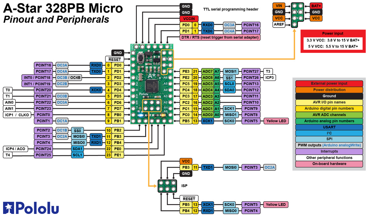 |
A-Star 328PB Micro pinout diagram. |
|---|
The A-Star 328PB Micro provides access to all 24 I/O lines of the microcontroller and ships with an Arduino-compatible serial bootloader; you can also use an AVR in-system programmer (ISP) for access to the entire chip. We recommend our USB AVR Programmer v2, which supports both programming interfaces and can be configured to run at either 3.3 V or 5 V.
Last but not least, we are continuing our plan of offering new products at the highest quantity price break at single unit quantities as an introductory celebration. That means that for the first 100 customers, you can get an A-Star 328PB Micro for just $3.87! (Must use coupon code AS328PBINTRO; click to add the coupon code to your cart.)
While we assemble (and design and document and ship and support) the boards here in Las Vegas, we still get the bare PC boards from China, where they are currently on holiday celebrating Chinese New Year. That is constraining how many units we can make at the moment, so we are limiting shipments to 5 units per customer. However, the introductory coupon has no quantity limit, and you can order more than five at that price if you would like. Backordered units are likely to ship within a few weeks.
Related products


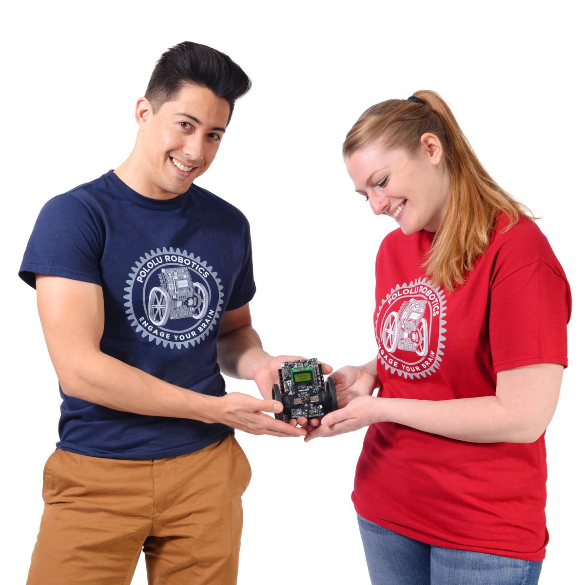
New Pololu Balboa T-Shirts!
 |
Our new Balboa T-shirts are here! They feature our latest robot, the Balboa 32U4 balancing robot, within an enlarged outline of the 43-tooth gear option for the Balboa gearbox, accompanied by our call to “Engage Your Brain”. These pre-shrunk cotton shirts are available in several colors (navy blue, cardinal red, or black) and a range of youth and adult sizes.
|
|
|


Related products

New products: MP6500 Stepper Motor Driver Carriers
 |
 |
We are excited to expand our colorful selection of stepper motor drivers with carrier boards for the brand new MPS MP6500 stepper motor driver!
Monolithic Power Systems’ MP6500 can drive a bipolar stepper motor from a 4.5 V to 35 V supply with up to 1/8-step microstepping. On our four-layer, 2 oz copper carrier boards, the MP6500 can deliver up to approximately 1.8 A per phase continuously without a heat sink or forced air flow, making this new module the highest-current stepper motor driver we carry among all the ones that share this form factor.
14 March 2018 Update: After further testing of more units, our initial characterization of the maximum continuous current capability was too high, so we have lowered it to 1.5 A. Please keep in mind that the exact maximum current you can get out of the driver at a given temperature will depend on your supply voltage and stepper motor characteristics.
 |
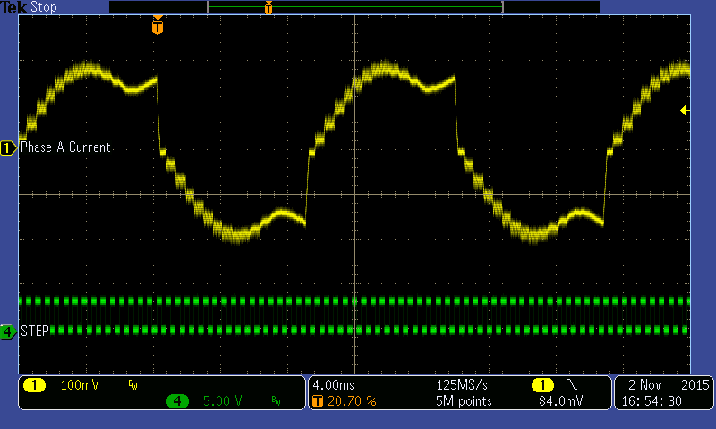
Unlike most other stepper motor drivers, the MP6500 features internal current sensing, which allows it to measure the motor’s coil current even during the off period of the PWM cycle. Combined with its automatic decay selection, this allows it to regulate the current especially accurately to produce smoother motion and higher speeds, as shown in the below oscilloscope capture from the MPS application note AN120 (1MB pdf).
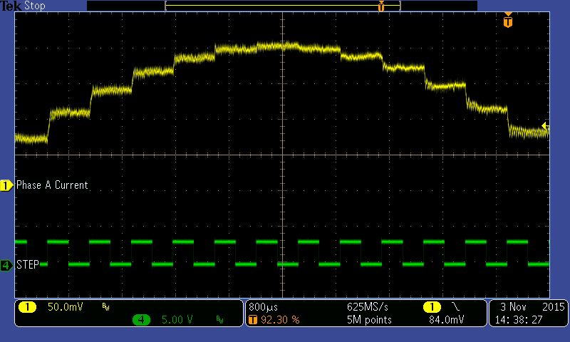 |
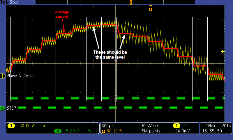
Compare this with waveforms from a stepper driver that uses a more typical method of peak current control:
|
|
In addition to a version with potentiometer current control like most of our other stepper motor drivers, we also offer the MP6500 on a board with digital current control. This second version enables a microcontroller to dynamically set the current limit in steps of 0.5 A (up to a maximum of 2 A) by simply driving one or two inputs low. Alternatively, supplying an analog voltage or PWM signal allows finer control of the limit within the 0 to 2 A range.
|
|


Introductory special: just $2.97 each! Must use coupon code MP6500INTRO, limited to first 200 customers, limit 5 per customer.
Related products


Want to move heavy loads? We've got the linear actuator for you!
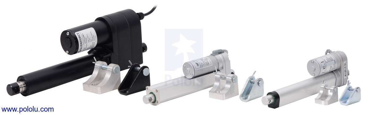 |
We have expanded our selection of Glideforce linear actuators from Concentric International to include their industrial-duty and medium duty series as steps up in power from their light-duty series that we have been offering for many years now.
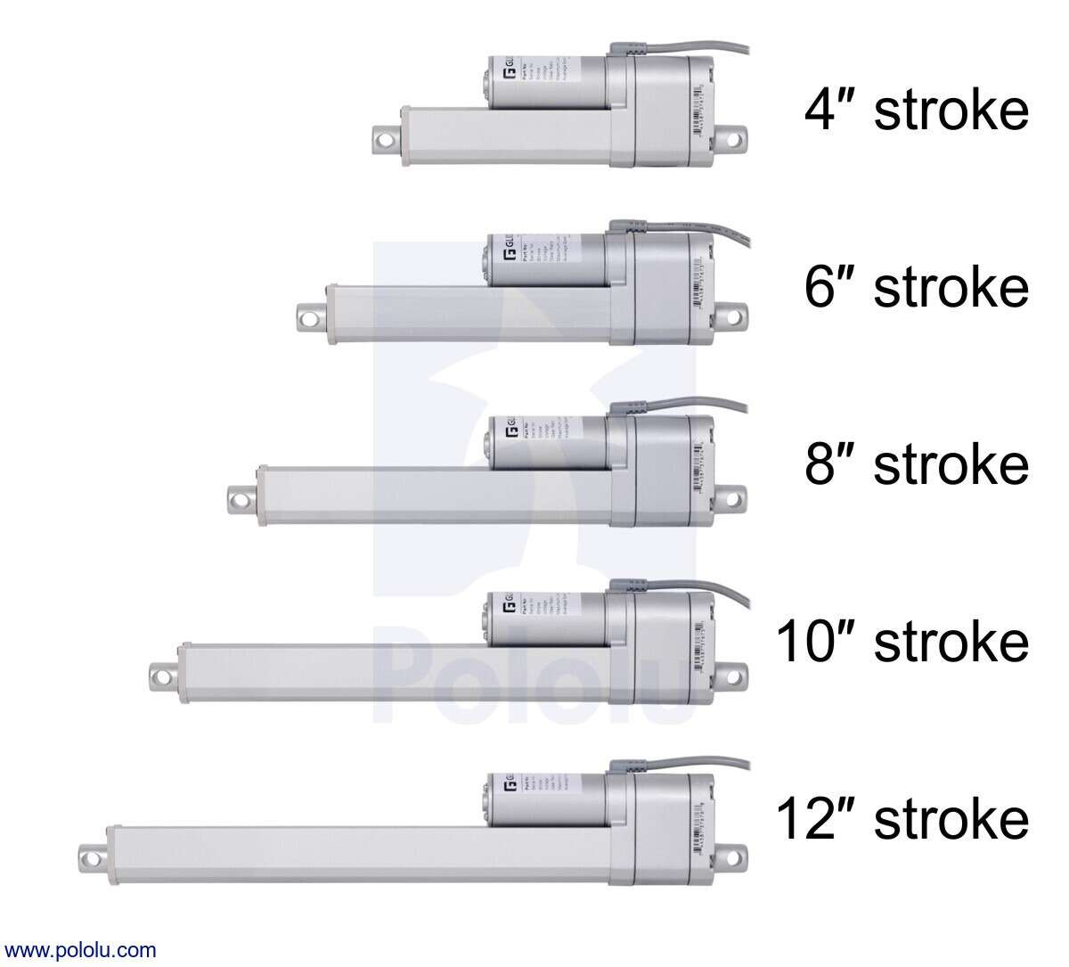
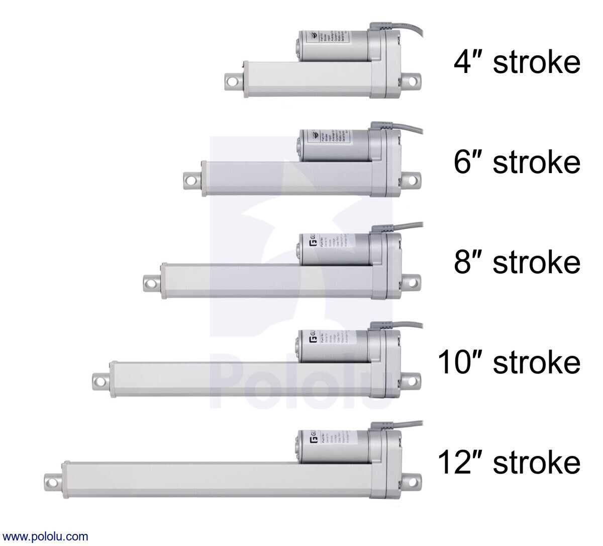
The medium-duty actuators are available in five different stroke lengths ranging from 4″ to 12″ and with or without feedback potentiometers, and they have a dynamic load rating of 225 lb, which means they can handle twice the load of their light-duty counterparts:
|
|
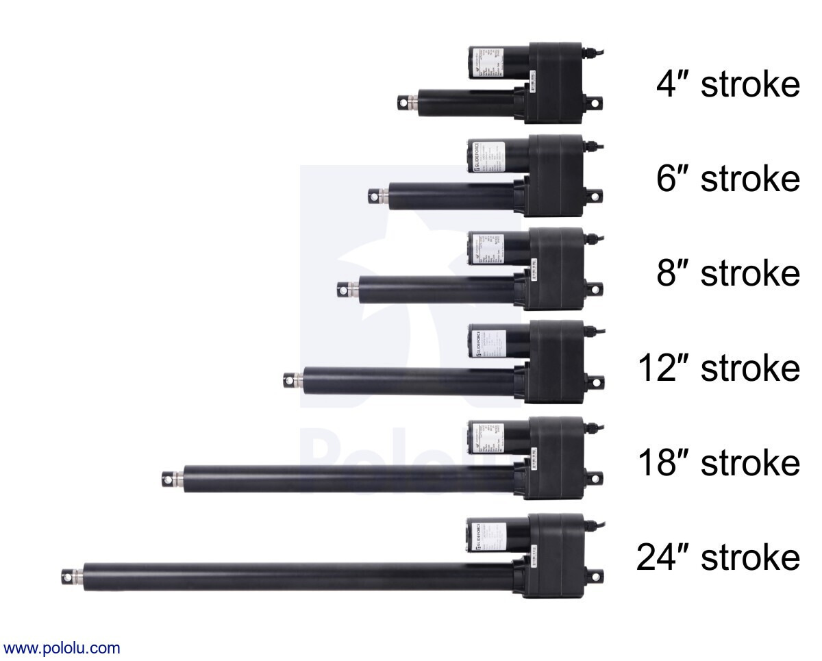
The industrial-duty actuators are real monsters compared to the medium-duty and light-duty units. The versions with an acme screw drive can handle dynamic loads up to 550 lb, and the versions with a ball screw drive (which is much more efficient than an acme screw) can handle dynamic loads up to a 1000 lb. Each drive option is available in six different stroke lengths ranging from 4″ to 24″ and with or without feedback potentiometers:
|
|
The following lets you compare all of our Glideforce linear actuator options:
| Actuator Type |
Max Dynamic Load |
No-Load Speed @ 12 V |
Current Draw @ 12 V |
Nominal Stroke Length |
With Feedback | Without Feedback | Approx. Weight |
|---|---|---|---|---|---|---|---|
| Light-Duty (LD) |
15 kgf [34 lbs] |
4.4 cm/s [1.7″/s] |
1.2 A – 3.2 A |
4″ | LACT4P-12V-05 | LACT4-12V-05 | 1.3 kg |
| 12″ | LACT12P-12V-05 | LACT12-12V-05 | 1.6 kg | ||||
| 50 kgf [110 lbs] |
1.5 cm/s [0.57″/s] |
2″ | LACT2P-12V-20 | LACT2-12V-20 | 1.2 kg | ||
| 4″ | LACT4P-12V-20 | LACT4-12V-20 | 1.3 kg | ||||
| 6″ | LACT6P-12V-20 | LACT6-12V-20 | 1.4 kg | ||||
| 8″ | LACT8P-12V-20 | LACT8-12V-20 | 1.5 kg | ||||
| 10″ | LACT10P-12V-20 | LACT10-12V-20 | 1.5 kg | ||||
| 12″ | LACT12P-12V-20 | LACT12-12V-20 | 1.6 kg | ||||
| Medium-Duty (MD) |
100 kgf [225 lbs] |
1.5 cm/s [0.58″/s] |
1.1 A – 4.6 A |
4″ | MD122004-P | MD122004 | 1.1 kg |
| 6″ | MD122006-P | MD122006 | 1.2 kg | ||||
| 8″ | MD122008-P | MD122008 | 1.3 kg | ||||
| 10″ | MD122010-P | MD122010 | 1.4 kg | ||||
| 12″ | MD122012-P | MD122012 | 1.5 kg | ||||
| Industrial-Duty (ID) with Acme screw drive |
250 kgf [550 lbs] |
1.7 cm/s [0.66″/s] |
2.4 A – 13.2 A |
4″ | LACT4-500APL | LACT4-500AL | 4.2 kg |
| 6″ | LACT6-500APL | LACT6-500AL | 4.4 kg | ||||
| 8″ | LACT8-500APL | LACT8-500AL | 4.7 kg | ||||
| 12″ | LACT12-500APL | LACT12-500AL | 5.3 kg | ||||
| 18″ | LACT18-500APL | LACT18-500AL | 6 kg | ||||
| 24″ | LACT24-500APL | LACT24-500AL | 7 kg | ||||
| Industrial-Duty (ID) with ball screw drive |
450 kgf [1000 lbs] |
1.7 cm/s [0.66″/s] |
2.4 A – 13.2 A |
4″ | LACT4-1000BPL | LACT4-1000BL | 4.6 kg |
| 6″ | LACT6-1000BPL | LACT6-1000BL | 4.9 kg | ||||
| 8″ | LACT8-1000BPL | LACT8-1000BL | 5.1 kg | ||||
| 12″ | LACT12-1000BPL | LACT12-1000BL | 5.6 kg | ||||
| 18″ | LACT18-1000BPL | LACT18-1000BL | 6.5 kg | ||||
| 24″ | LACT24-1000BPL | LACT24-1000BL | 7.4 kg | ||||
Note that we are currently out of stock of many of the industrial-duty versions, but we will be getting more as Concentric makes them available. For units where the expected lead time is several months, we have disabled backorders; please contact us if you are interested in placing an order now for one of those units.
To see all of our linear actuators, visit our linear actuator category.
New adjustable voltage regulators with multi-turn fine adjustment
 |
 |
I am excited to announce our first voltage regulators with multi-turn trimmer potentiometers! I have wanted to add multi-turn pots to our products for a long time, but the problem has been that they are really expensive. They also tend to be quite big, at least compared to many of our boards, which we try to keep compact, and the smaller, surface-mounted ones are especially expensive. My latest round of looking for lower-cost options did not pan out, but I decided to just give it a try with the expensive parts.
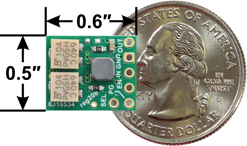
The new S9V11x regulators that feature these potentiometers are buck-boost regulators that can output a voltage that is lower, the same, or higher than the input voltage. There are also versions with a multi-turn pot for adjusting the undervoltage cutoff threshold, so that if you use these with batteries, you can prevent overdischarging them. With twelve turns of adjustment available, it’s much easier to precisely set the voltages on the modules than with the single-turn potentiometers we have used on other adjustable regulators.
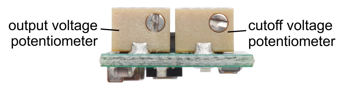 |
The output and cutoff multi-turn adjustment potentiometers on the S9V11x voltage regulators. |
|---|
While I have been talking mostly about the potentiometers, the main regulator is pretty magical, too, giving you quite a bit of power over a broad operating input range in a small size.
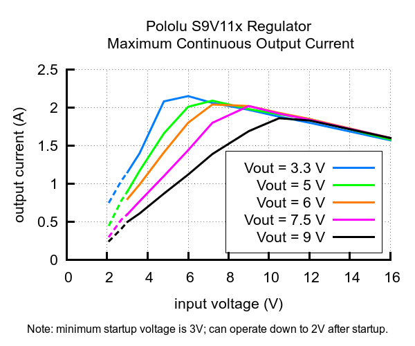 |
Typical maximum continuous output current of Step-Up/Step-Down Voltage Regulator S9V11x |
|---|
Our stock products are available in several combinations of adjustable and fixed output voltage and cutoff. If you have a higher-volume application, we can make them with fixed voltages wherever you need them. You could initially prototype your design with the adjustable version and then get fixed ones made once you know exactly what voltage you need.
| Regulator | Input (V) | Output (V) | Low-voltage cutoff | Size | Price | |
|---|---|---|---|---|---|---|
 |
#2868 S9V11MACMA | 2* – 16 | 2.5 – 9 (fine-adjust) | fine-adjust | 0.50″ × 0.60″ × 0.25″ | $13.95 |
 |
#2869 S9V11MA | 2.5 – 9 (fine-adjust) | – | $10.95 | ||
 |
#2870 S9V11F5S6CMA | 5 (6 V selectable) | fine-adjust | $10.95 | ||
| #2871 S9V11F3S5CMA | 3.3 (5 V selectable) | fine-adjust | $10.95 | |||
 |
#2872 S9V11F3S5 | 3.3 (5 V selectable) | – | 0.50″ × 0.60″ × 0.17″ | $7.95 | |
| #2873 S9V11F3S5C3 | 3.3 (5 V selectable) | 3 V (fixed) | $7.95 | |||
 |
#2836 S9V11F5 | 5 | – | 0.30″ × 0.45″ × 0.17″ | $8.95 | |
| * The regulator has a minimum start-up voltage of 3 V, but it can operate down to 2 V after startup. It is disabled when the input voltage is below the low-voltage cutoff. | ||||||
I am very interested to see what people think of the multi-turn adjustment feature. If these new regulators sell decently or customers ask for it, we will add the multi-turn potentiometers to our other regulator offerings. Is the extra expense worth it? Or do you know of a good, low-cost, multi-turn potentiometer we could consider for future products like this?
Related products


Home | Forum | Blog | Support | Ordering Information | Lists | Distributors | BIG Order Form | About | Contact
© 2001–2026 Pololu Corporation


