Support » Jrk G2 Motor Controller User’s Guide »
1. Overview
The second-generation Jrk G2 motor controllers are designed to enable easy closed-loop speed control or position control (but not both!) of a single brushed DC motor. They feature integrated support for analog voltage or tachometer (frequency) feedback and a variety of control interfaces–USB for direct connection to a computer, TTL serial and I²C for use with a microcontroller, RC hobby servo pulses for use in an RC system, and analog voltages for use with a potentiometer or analog joystick. A free configuration utility simplifies initial setup of the device, provides access to a wide array of configurable settings, and allows for in-system testing and monitoring of the controller via USB.
 |
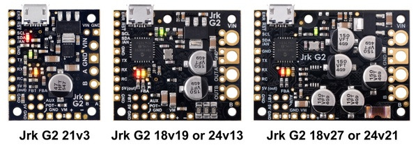
Side-by-side comparison of the different Jrk G2 USB Motor Controllers with Feedback. |
|---|
The table below lists the members of the Jrk G2 family and shows the key differences among them.
 Jrk G2 21v3 |
 Jrk G2 18v19 |
 Jrk G2 24v13 |
 Jrk G2 18v27 |
 Jrk G2 24v21 |
|
|---|---|---|---|---|---|
| Minimum operating voltage: |
4.5 V(1) | 6.5 V | 6.5 V | 6.5 V | 6.5 V |
| Recommended max operating voltage: |
28 V(2) | 24 V(3) | 34 V(4) | 24 V(3) | 34 V(4) |
| Max nominal battery voltage: |
24 V | 18 V | 28 V | 18 V | 28 V |
| Max continuous current (no additional cooling): |
2.6 A | 19 A | 13 A | 27 A | 21 A |
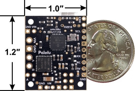
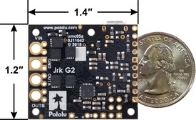
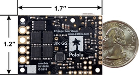
| Dimensions: | 1.0″ × 1.2″ | 1.4″ × 1.2″ | 1.7″ × 1.2″ | ||
1 The 5V logic voltage drops when powered from a supply below about 5.2 V.
2 Transient operation (< 500 ms) up to 40 V.
3 30 V absolute max.
4 40 V absolute max.
Features and specifications
- Easy open-loop or closed-loop control of one brushed DC motor
- A variety of control interfaces:
- USB for direct connection to a computer
- TTL serial operating at 5 V for use with a microcontroller
- I²C for use with a microcontroller
- RC hobby servo pulses for use in an RC system
- Analog voltage for use with a potentiometer or analog joystick
- Feedback options:
- Analog voltage (0 V to 5 V), for making a closed-loop servo system
- Frequency, for closed-loop speed control using pulse counting (for higher-frequency feedback) or pulse timing (for lower-frequency feedback)
- None, for open-loop speed control
- Note: the Jrk does not support using quadrature encoders for position control
- Ultrasonic 20 kHz PWM for quieter operation (can be configured to use 5 kHz instead)
- Simple configuration and calibration over USB with free configuration software utility (for Windows, Linux, and macOS)
- Configurable parameters include:
- PID period and PID coefficients (feedback tuning parameters)
- Maximum current
- Maximum duty cycle
- Maximum acceleration and deceleration
- Error response
- Input calibration (learning) for analog and RC control
- Optional CRC error detection eliminates communication errors caused by noise or software faults
- Reversed-power protection
- Field-upgradeable firmware
- Optional feedback potentiometer disconnect detection
 |
Jrk G2 21v3 USB Motor Controller with Feedback, bottom view with dimensions. |
|---|
|
|
Note: This guide only applies to the Jrk G2 motor controllers, which have black circuit boards. If you have one of the first-generation Jrk 21v3 or Jrk 12v12 controllers, which have green circuit boards, you can find their user’s guide here.


