Support » Tic Stepper Motor Controller User’s Guide » 1. Overview »
1.1. Available versions
The Tic family consists of five different controllers: the Tic T500, Tic T834, Tic T825, Tic T249, and Tic 36v4. The main differences between those boards are mentioned in Section 1.
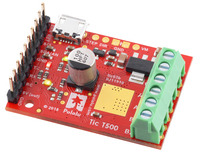
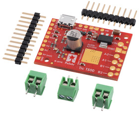
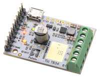
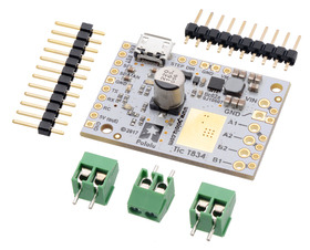
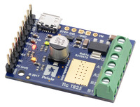
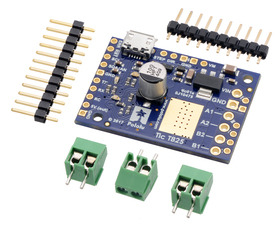
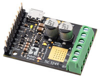
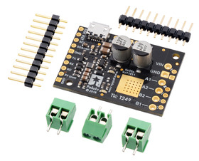
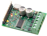
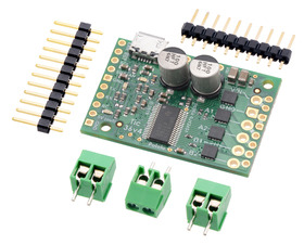
Each Tic controller is each available in two versions: with terminal blocks and 0.1″ male headers installed, as shown in the left pictures above, and with through-hole connectors included but not soldered in, as shown in the right pictures above. The versions with connectors installed allow for all of the main features to be used without any additional soldering required as the stepper motor and power leads can be connected to the board via terminal blocks and the signal pins can be connected to the board by 0.1″ connectors, such as premium jumper wires, cables made from wires with pre-crimped terminals, and servo cables. The connector-free versions allow for custom installations, such as soldering the included 0.1″ male header pins pointing down for use in a breadboard or soldering wires directly to the board.
- Tic T500 with terminal blocks and 0.1″ male headers installed
- Tic T500 with through-hole connectors included but not soldered in
- Tic T834 with terminal blocks and 0.1″ male headers installed
- Tic T834 with through-hole connectors included but not soldered in
- Tic T825 with terminal blocks and 0.1″ male headers installed
- Tic T825 with through-hole connectors included but not soldered in
- Tic T249 with terminal blocks and 0.1″ male headers installed
- Tic T249 with through-hole connectors included but not soldered in
- Tic 36v4 with terminal blocks and 0.1″ male headers installed
- Tic 36v4 with through-hole connectors included but not soldered in
The connector-free versions include the following connectors:
- Three 2-pin 3.5mm screw terminal blocks – you can combine these by sliding them together and use them with the larger motor and power holes.
- 1×10 breakaway male header pin strip – this matches the 10 holes along the side of the board opposite the power and motor connections.
- 1×12 breakaway male header pin strip – this can be broken into smaller pieces and used with the other 0.1″ holes on the board as desired.
