Support » Pololu Zumo 32U4 Robot User’s Guide » 3. The Zumo 32U4 in detail »
3.9. Expansion areas
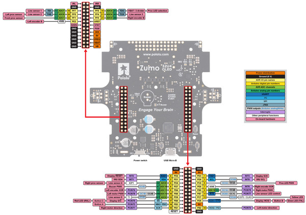
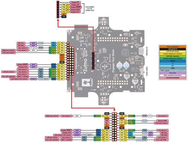
The top expansion areas on the Zumo 32U4 main board (in two 2×13 groups of pins near the left and right edges) break out all of the ATmega32U4 microcontroller’s general-purpose I/O lines and provide access to various power inputs and outputs. Some of these pins are also broken out in the front expansion area, where the front sensor array connects. The following diagrams identify the locations of these pins and the hardware associated with them (OLED version pictured below). These diagrams are also available as printable PDFs:
- Zumo 32U4 OLED main board pinout diagram (701k pdf)
- Zumo 32U4 main board pinout diagram (546k pdf) (original LCD version)
 |
Zumo 32U4 OLED top expansion pinout. |
|---|
 |
Zumo 32U4 OLED front expansion and display connector pinout. |
|---|
For more information about the ATmega32U4 microcontroller and its peripherals, see Atmel’s ATmega32U4 documentation.


