Pololu Blog »
Posts tagged “sample projects”
You are currently viewing a selection of posts from the Pololu Blog. You can also view all the posts.
Popular tags: community projects new products raspberry pi arduino more…
Video: LVBots May 2018 line following competition
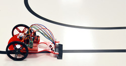
LVBots held a line following competition at Pololu on May 24th. This time we had our “classic” line following course like in previous competitions, and an “advanced” course with gaps, intersections, tighter turns, and shortcuts. Continued…
How to make a Balboa robot balance, part 5: popping up and driving around
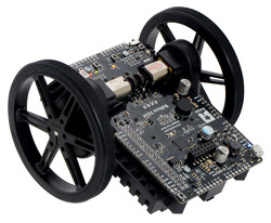
This is the fifth and final post in a series about how to make a Balboa 32U4 robot balance. In earlier posts I covered everything you need to get the robot balancing. In this post I will talk about how to get your Balboa to perform some fun and challenging maneuvers.
If you have been following along, you should now have your robot using its inertial sensors, motors, and encoders together to balance in place. Now it’s time to get it moving! Our first challenge will be to get it to “pop up” from a resting position into a balancing position. Then I will show how you can get the Balboa to drive around while balancing. Continued…
Building a Raspberry Pi robot with the Romi chassis
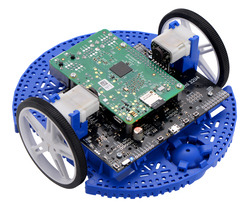
This tutorial shows how to build a basic Raspberry Pi robot with the Romi chassis and the Romi 32U4 Control Board, our Arduino-compatible microcontroller board designed specifically for the Romi. With this setup, the powerful Raspberry Pi can take care of high-level tasks like motion planning, video processing, and network communication, while the Romi 32U4 Control Board takes care of low-level tasks that the Pi is incapable of, such as motor control and sensing. Continued…
How to make a Balboa robot balance, part 4: a balancing algorithm
This is the fourth post in a series about how to make a Balboa 32U4 robot balance. In earlier posts I covered the basic sensors and mechanical parts used for balancing; in this post I will show you how to put everything together to make the robot actually balance.
From earlier posts we have obtained six basic variables for use in balancing: Continued…
How to make a Balboa robot balance, part 3: encoders
This is the third post in a series about how to make a Balboa 32U4 robot balance. Last week I talked about inertial sensors, especially the gyro. In this post I will talk about the Balboa’s built-in encoders, which allow accurate measurements of motor speed and distance.
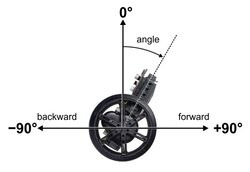
To get your Balboa to balance, you will soon need to create a balancing algorithm, a program that takes sensor input and computes the appropriate motor speed settings to keep the robot upright. So far our only inputs, both from the gyro, are the rate of rotation and current angle of the robot. These are not quite enough to make a good balancer. To see why, suppose that your program tries to balance by holding the angle at a constant 90°. If your definition of 90° is even slightly off-balance, the robot will need to keep accelerating, driving faster and faster to maintain it, until it reaches top speed or hits an obstacle. You might be able to account for this by using the motor output settings themselves as an input to your algorithm, but this is difficult, especially at the low speeds used for balancing. Also, even if you can avoid accelerating, your robot will gradually drift in one direction or the other. The Balboa’s encoders are valuable additional sensor inputs that allow you to measure how fast the wheels are actually turning, so you can directly control acceleration and drift. As a bonus, encoders are great for driving straight, precision turns, and navigation. Continued…
How to make a Balboa robot balance, part 2: inertial sensors
This is the second post in a series about how to make a Balboa 32U4 robot balance. Last week I talked about selecting mechanical components. In this post I will cover the inertial sensors included on the Balboa’s control board and how to use them in your code.
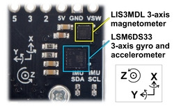
The key to Balboa’s balancing ability is the built-in ST LSM6DS33 IMU chip, which combines a 3D gyroscope and a 3D accelerometer. The Balboa also includes an ST LIS3MDL 3-axis magnetometer. Both sensors are connected to the AVR via I²C, giving it access to a total of nine sensor channels. These nine channels can be used in software to make an AHRS (attitude and heading reference system), a system that gives the robot a sense of its orientation in three dimensions. AHRS software is particularly important in aviation/drone applications, but for basic balancing, you don’t need anything that complicated. In fact, a single gyro channel is enough to determine the robot’s angle of rotation relative to vertical. The gyroscope’s y-axis channel measures the Balboa’s forward/backward rate of rotation; that is the channel we will be looking at here. Continued…
How to make a Balboa robot balance, part 1: selecting mechanical parts
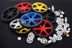
This is the first post in a series about how to make a Balboa 32U4 robot balance. Today I will talk about selecting mechanical parts for your Balboa. We offer a variety of gearmotors and wheels that work with the Balboa, and the Balboa kit includes five different gear ratios for the external gearbox, so even without considering non-standard modifications, there are many possible configurations of the robot. In this post I will give you some guidance about choosing the right parts. Continued…
LED strip code used in Pololu Christmas video
We added the code we used for the LEDs in our Christmas video last week to our GitHub page. Ben cleaned it up a bit and added lots of comments, so we hope it’s helpful if you want to use it as a base to write some awesome sequences for your own LED strips.
In case you missed the video, here it is again:
A Pololu Christmas Story (with LEDs!)
Merry Christmas! We got some new LED strips in a week or so ago that are based on the WS2812B. I was pretty excited to play around with them, so I decided I would decorate Ben’s house and make him film this video with me. (I know. I should have decorated my own house, but I live far from the office… and don’t have a wife.)
We should have the code we used for the LEDs available on our github page in a couple of days.
Sample project: Wixel USB Joystick
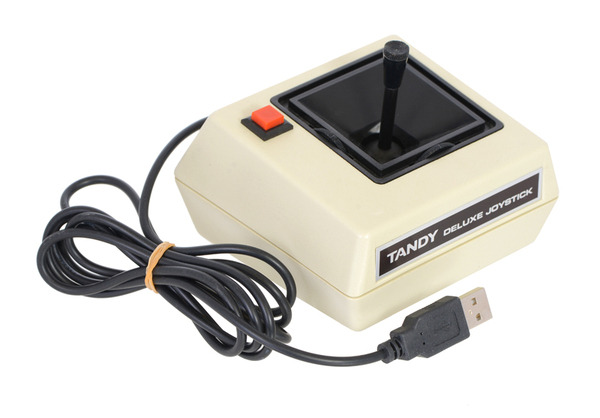 |
We’ve published a new sample project that shows you how to use the Wixel and its Joystick App to convert a non-USB joystick into a USB device. This guide walks you through the whole process: all you have to do is make the right wiring connections and configure the app on the Wixel; no programming is required.
Check out the project page to see how we converted a Tandy Deluxe Joystick and learn how to adapt your own input device with a Wixel!
Related post: Joystick App for Wixel now available
