MyoWare Muscle Sensor
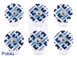
The MyoWare Muscle Sensor from Advancer Technologies measures, filters, rectifies, and amplifies the electrical activity of a muscle and produces an analog output signal that can easily be read by a microcontroller, enabling novel, muscle-controlled interfaces for your projects. Note: This product requires electrodes; these are not included, but they are available separately in packs of six.
| Description | Specs (6) | Pictures (4) | Resources (3) | FAQs (0) | On the blog (3) | Distributors (0) |
|---|
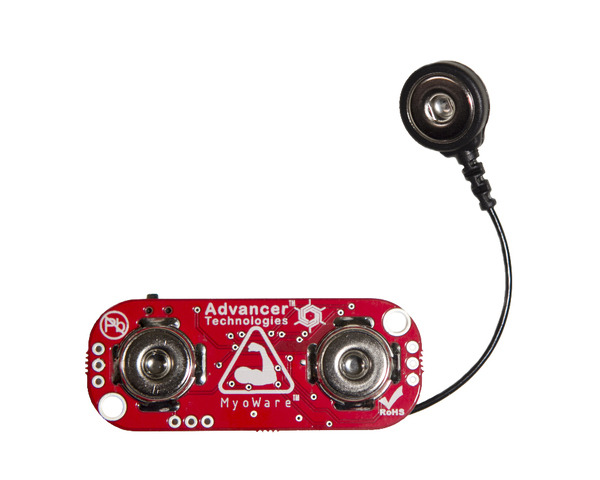
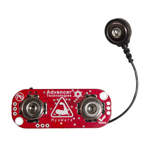
Note: This product does not include electrodes; they are available separately in packs of six. To use the sensor, an electrode must be connected to each of the sensor’s three snap connectors (two on the PCB and the third at the end of the black reference electrode cable).
 |
Overview
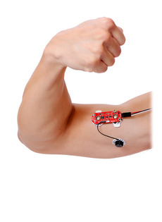
This muscle sensor from Advancer Technologies measures a muscle’s activity by monitoring the electric potential generated by muscle cells. This is referred to as electromyography (EMG). The sensor amplifies and processes the complex electrical activity of a muscle and converts it into a simple analog signal that can easily be read by any microcontroller with an analog-to-digital converter (ADC), such as an A-Star or Arduino – or even a Maestro servo controller like we show in this blog post. As the target muscle group flexes, the sensor’s output voltage increases. The exact relationship between the output voltage and the muscle activity can be fine-tuned using an on-board gain potentiometer.
The MyoWare Muscle Sensor is an updated version of Advancer Technologies’ older Muscle Sensor v3 with a number of improvements, notably single-supply operation (no need for a negative voltage supply) and built-in snap connectors for electrodes. Other new features include a raw EMG output, reverse power protection, a power switch, and LED indicators.
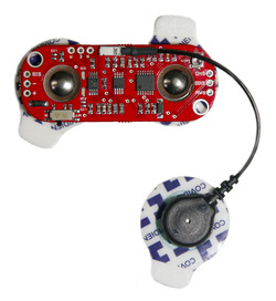
In order to attach to skin, the sensor requires three electrodes (not included) that snap into the sensor’s snap-style connectors, which make it easy to attach and detach electrodes. Two connectors are located directly on the PCB, and the third is located at the end of the attached reference electrode cable. The board’s pins have a 0.1″ pitch and work with 0.1″ male headers and 0.1″ female headers.
|
|
For more detailed information about the muscle sensor, including instructions on how to use it, see the Advancer Technologies MyoWare Muscle Sensor datasheet (1MB pdf). Example Arduino programs can be found on the MyoWare GitHub page.
Features
 |
- Dimensions: 2.1″ × 0.8″ (excluding reference electrode cable, which is about 3″ long)
- Operating voltage: 2.9 V to 5.7 V (unlike previous sensor versions, no negative supply is required)
- Analog voltage output from 0 V to +Vs (supply voltage)
- Adjustable gain
- Both EMG envelope and raw EMG outputs available
- Embedded electrode connectors – electrodes snap directly into MyoWare (alternatively, external electrode cables can be connected)
- LED Indicators – one power LED, and one LED that brightens when the muscle is flexed
- Power switch
- Reverse voltage protection
- Two mounting holes (suitable for M3 or #4 screws)
- Informative user’s guide (1MB pdf)
The preferred way to power the MyoWare sensor is from the same logic voltage as the rest of your system (for example, 5 V when used with a 5 V microcontroller). If you power the sensor from a battery or another supply with a higher voltage, the output can be as high as the supply voltage (Vs), and we recommend that you take precautions (such as adjusting the gain) to make sure that the signal does not exceed what the rest of the system can handle.
