Advancer Technologies Muscle Sensor v3
The Muscle Sensor v3 from Advancer Technologies measures, filters, rectifies, and amplifies the electrical activity of a muscle and produces an analog output signal that can easily be read by a microcontroller, enabling novel, muscle-controlled interfaces for your projects. This small board measures 1″ × 1″ and includes six electrodes and a 24″ sensor cable.
| Description | Specs (3) | Pictures (4) | Resources (5) | FAQs (0) | On the blog (1) | Distributors (0) |
|---|
This sensor has been replaced by the newer MyoWare Muscle Sensor from Advancer Technologies, which features a number of improvements including single-supply operation (no need for a negative voltage supply) and built-in snap connectors for electrodes.
 |
Overview
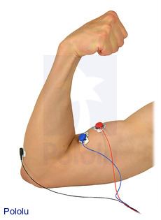
This muscle sensor from Advancer Technologies measures a muscle’s activity by monitoring the electric potential generated by muscle cells. This is referred to as electromyography (EMG). The sensor amplifies and processes the complex electrical activity of a muscle and converts it into a simple analog signal that can easily be read by any microcontroller with an analog-to-digital converter (ADC), such as an A-Star or Arduino – or even a Maestro servo controller as shown in the video above. As the target muscle group flexes, the sensor’s output voltage increases. The exact relationship between the output voltage and the muscle activity can be fine-tuned using an on-board gain potentiometer.
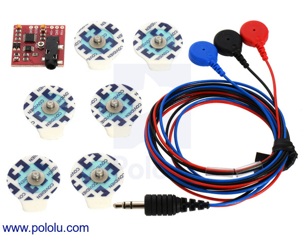
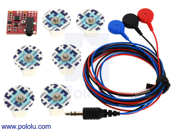
A cable is included for connecting three electrodes to the muscle sensor board. One end of the cable is terminated with a single 3.5 mm audio-style connector that can be plugged directly into the board. The opposite end has three snap-style connectors to make it easy to attach and detach electrodes. Please note that the six included sample electrodes are intended to be single use; replacement electrodes are available directly from Advancer Technologies or from medical supply stores. The board’s power and signal pins have a 0.1″ pitch and work with 0.1″ male headers and 0.1″ female headers.
For more detailed information about the muscle sensor, including instructions on how to use it, see the Advancer Technologies Muscle Sensor v3 user’s manual (409k pdf). Example Arduino programs can be found on their GitHub page.
Warning: This sensor’s output signal can be as high as the supply voltage (Vs). If you are using a supply voltage higher than the rest of your system can handle, we recommend using the gain potentiometer to adjust the sensor’s maximum output to an appropriate voltage before connecting the signal line to the rest of your system. Alternatively, you could lower the output voltage using an external circuit such as a voltage divider before connecting it to your microcontroller.
|
|
Features
 |
- Dimensions: 1″ × 1″ (1.13″ × 1″ including audio-style jack)
- Analog voltage output from 0 V to +Vs (supply voltage)
- Adjustable gain
- Typical operating voltage of ±5 V
- Breadboard compatible
- 3.5 mm audio-style plug for easy connection
- Informative user’s guide (409k pdf)
Caution: This product needs a positive and negative reference voltage. Two power supplies are required. The sensor has a maximum operating voltage of ±18 V; however, we recommend using no higher than ±9 V to minimize the risk of electric shock. In our experience, supplying ±3.7 V is more than enough to get good performance from the sensor.
Included hardware
The muscle sensor ships with all of the components shown below: the sensor board, a 24″ (61 cm) cable for connecting electrodes to the sensor board, and six 24 mm sample electrodes. The power and signal pins work with standard 0.1″ male headers or 0.1″ female headers (not included).
 |
