Motion Control Modules » Brushed DC Motor Controllers » Pololu Qik Dual Serial Motor Controllers »
Pololu Qik 2s15v9 Dual Serial Motor Controller
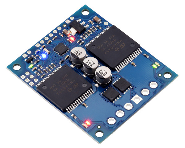
This powerful motor controller allows variable speed and direction control of two large, brushed DC motors using a simple serial interface and provides several advanced features, such as motor acceleration control and configurable current limiting. Automatic baud detection up to 115.2 kbps and inputs for both RS-232 and TTL serial make it easy to add motors to your microcontroller- or computer-based project. The operating voltage range is 6 to 24 V; the continuous current per channel is up to 12 A (30 A peak).
 Compare all products in Pololu Qik Dual Serial Motor Controllers.
| Description | Specs (14) | Pictures (9) | Resources (7) | FAQs (0) | On the blog (0) | Distributors (1) |
|---|
Overview
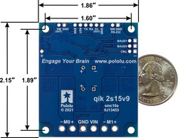 |
The Qik 2s15v9 adds a comprehensive yet easy-to-use, high-power option to Pololu’s line of motor controllers. The compact board allows any microcontroller or computer with a serial port to drive two brushed DC motors with full direction and speed control, providing up to 12 A (continuous) per motor channel without a heat sink and tolerating peaks as high as 30 A.
The improvements over competing products include:
- high-frequency PWM to eliminate switching-induced motor shaft hum or whine
- a robust, high-speed communication protocol with user-configurable error condition response
- visible LEDs and a demo mode to help troubleshoot problematic installations
- reverse power protection
For a lower-power version of this controller, please consider the Qik 2s9v1. For similar devices that support additional features and control interfaces, please consider the Simple High-Power Motor Controllers and Jrk G2 Motor Controllers with Feedback.
Main Features of the Qik 2s15v9
 |
- Simple bidirectional control of two DC brush motors.
- 6 V to 24 V operating supply range.
- 12 A maximum continuous current per motor (30 A peak).
- Logic-level, non-inverted, two-way serial control for easy connection to microcontrollers or robot controllers.
- RS-232-level, one-way serial control for easy connection to a PC serial port.
- Optional automatic baud rate detection from 1200 bps to 115.2 kbps.
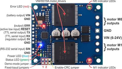
- Seven on-board indicator LEDs (power, status/heartbeat, error indicator, and motor indicators) for debugging and feedback.
- Advanced features include configurable acceleration, motor current feedback, and current limiting.
- Error output to make it easier for the main controller to recover from an error condition.
- Optional motor shutdown on error or serial timeout for additional safety.
- Jumper-enabled demo mode allows initial testing without any programming.
- Optional CRC error detection eliminates serial errors caused by noise or software faults.
- Comprehensive user’s guide.
Specifications
| Motor channels: | 2 |
|---|---|
| Operating voltage: | 6 – 24 V |
| Continuous output current per channel: | 12 A |
| Peak output current per channel: | 30 A |
| Auto-detect baud rate range: | 1200 – 115,200 bps |
| Available fixed baud rates: | 115,200 bps, 38,400 bps, 9600 bps |
| Available PWM frequencies: | 19.7 kHz, 9.8 kHz, 2.5 kHz, 1.2 kHz, 310 Hz, 150 Hz |
| Reverse voltage protection?: | Y |
| Motor driver: | VNH5019 x2 |
Included Hardware
|
|
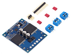
The Qik ships with a 12×1 straight 0.100" male header strip, a 3×2 straight 0.100" male header strip, three 2-pin terminal blocks, and three red shorting blocks.
For the most compact installation, you can solder wires directly to the Qik pins themselves and skip using the included hardware. For high-current installations, you should avoid using the supplied terminal blocks, which are rated for up to 15 A, and instead directly solder the motor and power supply wires to the pads.
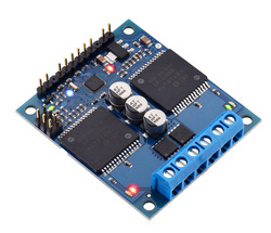
The included hardware allows you to make less permanent connections. You can break the 12×1 header strip into a 6×1 piece and two 2×1 pieces and solder these strips into the Qik’s logic pins where you plan on making connections, or you can use a pair of pliers to pull out the two header pins in the original 12×1 strip for which the Qik has no holes and solder the entire strip to the Qik’s logic pins. You can see this latter approach in the picture above. You can then make your own cables that have female headers on them and plug these onto the male headers on your Qik, or you can solder the pins to the other side of the board and simply plug your Qik into a breadboard. You might also consider using a 0.100" right-angle male header strip (not included) for a lower profile.
The 3×2 header strip can be soldered to the jumper pins as shown above, which lets you make use of the included shorting blocks, and the included terminal blocks lock together to make a single, 6-pin strip that you can solder to the power side of the board.
Sample Code
We have written a basic Arduino library for the Qik Dual Serial Motor Controllers that makes it simple to interface these controllers with an Arduino. The library handles the details of serial communication with the Qik, allowing two brushed DC motors to be controlled easily.
Comparison to the original Qik 2s12v10
The 2s15v9 is intended as a replacement for the original Qik 2s12v10, which was based on motor drivers that have now been discontinued. The 2s15v9 uses the same firmware, so the interface is unchanged, and has the same footprint and pinout. Additionally, the current output capabilities are approximately the same, and the operating voltage range is wider, so the 2s15v9 should be able to serve as a drop-in replacement for the 2s12v10 in most applications. Here are the key differences between the two controllers:
- The Qik 2s15v9 operates from 6 V to 24 V, compared to 6 V to 16 V for the 2s12v10.
- The Qik 2s15v9 has its reverse voltage protection on the high side while the Qik 2s12v10 has it on the low side. The 2s15v9’s reverse-protected input voltage is accessible through a 0.1″-pitch through-hole labeled VM; this pin on the 2s12v10 was labeled “VIN (out)” and provided direct access to the input voltage.
- The Qik 2s15v9 adds a third electrolytic capacitor, and the through-holes for optionally adding an axial capacitor have changed (the positive through-hole is in a different location, and there is no longer a dedicated ground through-hole for an axial capacitor, so one of the general ground pins would need to be used).
