Support » Pololu Motoron Motor Controller User’s Guide » 3.2. Connecting everything »
3.2.2. Connecting a micro Motoron with a serial interface
This section explains how to connect motor power, motors, and a microcontroller to the Motoron M1U550, M2U550, M1U256, and M2U256, micro-sized controllers with a UART serial interface.
 |
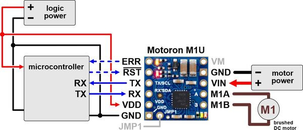
Typical wiring diagram for connecting a microcontroller to a Motoron M1U256/M1U550 Single Serial Motor Controller. |
|---|
 |
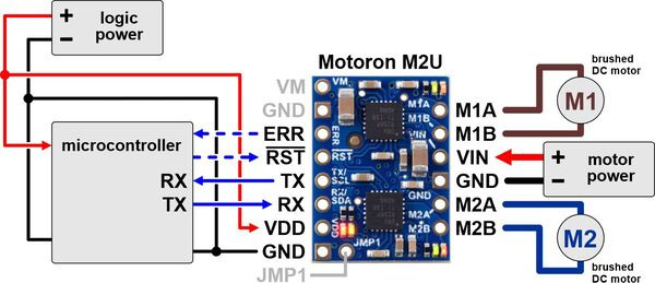
Typical wiring diagram for connecting a microcontroller to a Motoron M2U256/M2U550 Dual Serial Motor Controller. |
|---|
 |
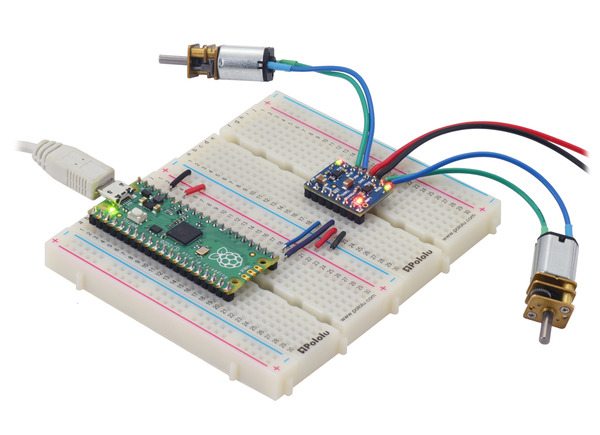
A Raspberry Pi Pico on a breadboard using a Motoron M2T550/M2U550 Dual Motor Controller to control two motors. |
|---|
Making connections
You can buy a version of the Motoron that comes with male header pins already soldered, or you can buy a version with header pins included and do the soldering yourself. After your Motoron has header pins securely soldered to it, you can push the Motoron into a breadboard or connect its pins to jumper wires. Alternatively, you can make connections by directly soldering wires to the board. Regardless of which of these methods you choose, soldering is necessary to make reliable connections.
Connecting motor power and motors
The negative terminal of the motor power supply should be connected to the GND pin on the Motoron that is adjacent to VIN. The positive terminal of the motor power supply should be connected to the VIN pin. Note that connecting power to VIN does not power the Motoron’s microcontroller and does not cause any LEDs to turn on.
Each motor should have one lead connected to an MxA pin (M1A or M2A) and the other lead connected to the MxB pin with the matching motor number. The Motoron’s concept of “forward” corresponds to MxA driving high while MxB drives low, so you might consider this when deciding which motor lead connects to which Motoron pin. You can also flip the wires later if you want to flip the direction of motion.
Connecting a controller
You will need a controller with a UART serial interface to send commands to the Motoron. The Motoron’s GND pin should be connected to a ground pin of the controller board. The Motoron’s RX pin should be connected to the TX pin of the controller board. If you want to read data from the Motoron, then the Motoron’s TX pin should be connected to the RX pin of the controller board. The Motoron’s logic voltage (VDD) should be connected to the logic voltage supply of the controller board (the allowable logic voltage range can be found in the specifications for your particular Motoron). The Motoron does not supply power to the controller board.
Once you make the GND and logic power connections and turn on the logic power, you should see the Motoron’s yellow LED blink. The red LED will also turn on unless something is communicating with the Motoron and causing it to turn the LED off.


