Support » Pololu Dual VNH5019 Motor Driver Shield User’s Guide » 6. Customizing the Shield »
6.b. Accessing ENA/DIAGA and ENB/DIAGB Pins Separately
The VNH5019 motor drivers have separate enable/diagnostic pins for the A and B half bridges, but the shield combines these lines into a single enable/diagnostic pin for each motor driver in order to decrease the number of I/O lines required to monitor motor faults. This combined line is sufficient for most applications, but you can modify the board to get independent access to MxENA/DIAGA and MxENB/DIAGB if you want the additional information.
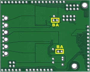
There are two pairs of 0.1″-spaced holes on the shield labeled “M1EN A=B” and “M2EN A=B”. These pairs are connected on the underside of the PCB by a thin trace, with the hole labeled “A” connecting to the ENA/DIAGA pin of the corresponding motor driver and the hole labeled “B” connecting to the ENB/DIAGB pin of the motor driver:
 |
Cuttable traces on the dual VNH5019 motor driver shield for separately accessing ENA/DIAGA and ENB/DIAGB. |
|---|
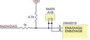
The following diagram shows the relevant section of the board schematic:
 |
Schematic diagram of the enable/diagnostic circuit on the Pololu dual VNH5019 motor driver shield. |
|---|
To separately access both ENA/DIAGA and ENB/DIAGB, you can use a knife to cut the trace between the through-hole pair and then run a wire to the right (B) pin. Note that once the connection between the two pins is severed, only ENA/DIAGA will have the required pull-up resistor; you will need to add a separate pull-up resistor for the ENB/DIAGB pin, or connect it to a microcontroller I/O line with a built-in pull-up resistor enabled. Also, you might consider adding a 1k current-limiting resistor in series with the ENB/DIAGB connection as a safeguard against incidental shorts.
You can later use a shorting block to restore the default combined EN/DIAG line if you populate the severed hole pair with a 2×1 piece of the included 0.1″ male header strip.


