Support » Pololu Maestro Servo Controller User’s Guide » 7. Wiring Examples »
7.c. Connecting to a Microcontroller
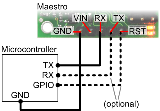 |
Diagram showing how to connect the Micro Maestro servo controller to a microcontroller. |
|---|
The Maestro can accept TTL serial commands from a microcontroller. To connect the microcontroller to the Maestro, you should first connect the ground line of the microcontroller to the ground line of the Maestro. Then connect the TX (serial transmit) line of the microcontroller to the RX line of the Maestro so that the microcontroller can send commands. If you need to receive serial responses from the Maestro, then you will need to connect the RX (serial receive) line of the microcontroller to the Maestro’s TX line. For more information on the different serial modes and commands, see Section 5.
If you want your microcontroller to have the ability to reset the Maestro, then connect the RST line of the Maestro to any general-purpose I/O line of the microcontroller. You should have the I/O line tri-stated or at 5 V when you want the Maestro to run and drive it low (0 V) temporarily to reset the Maestro.
If you want your microcontroller to have the ability to detect errors from the Maestro using a digital input instead of the serial command, or you want to receive direct feedback from the user script, then connect the ERR line of the Maestro to any general-purpose I/O line of the microcontroller. The ERR line is only available on the Mini Maestro 12-, 18-, and 24-channel servo controllers. See Section 1.b for more information about the ERR line.
Related products


Home | Forum | Blog | Support | Ordering Information | Wish Lists | Distributors | BIG Order Form | About | Contact
© 2001–2024 Pololu Corporation
