Pololu Blog »
Pololu Blog (Page 18)
Welcome to the Pololu Blog, where we provide updates about what we and our customers are doing and thinking about. This blog used to be Pololu president Jan Malášek’s Engage Your Brain blog; you can view just those posts here.
Popular tags: community projects new products raspberry pi arduino more…
New product: STSPIN820 Stepper Motor Driver Carrier with 1/256 microstepping
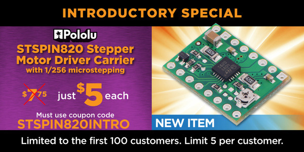
We have yet another new stepper motor driver carrier in our popular 16-pin, 0.6″ × 0.8″ form factor, this time for STMicro’s STSPIN820, which offers 1/256 step microstepping! ST actually has their own similar evaluation board, the EVALSP820-XS, but the STSPIN820 chip has a non-inverted Enable input, which is inverted compared to most other stepper motor driver ICs out there, and they expose the pin that way on their version of the board. We have thoughtfully added a transistor-based inverter so that our board is more likely to work as a drop-in replacement (or upgrade!) for the stepper driver boards you already have. In our tests, the Pololu carrier supported a substantially higher maximum current than the ST eval board (around 900 mA compared to 720 mA, probably due to our board having four layers vs. two layers for the ST eval board), and as of this writing (27 November 2018), our board is also priced lower.
You can see the full schematic for all the details (this schematic is also available as a downloadable pdf (109k pdf)):
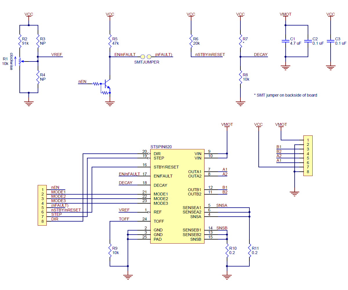 |
Schematic diagram of the STSPIN820 Stepper Motor Driver Carrier. |
|---|
With our release earlier in November of compact carriers for Toshiba’s TB67S249FTG and TB67S279FTG stepper motor drivers, we now offer ten different stepper motor driver modules in this compact size:
 A4988 (original) |
 A4988, Black Ed. |
 DRV8825 |
 DRV8834 |
 DRV8880 |
 MP6500, Pot. CC |
 MP6500, Digital CC |
 TB67S279FTG |
 TB67S249FTG |
 STSPIN820 |
|
|---|---|---|---|---|---|---|---|---|---|---|
| Driver chip: | A4988 | DRV8825 | DRV8834 | DRV8880 | MP6500 | TB67S279FTG | TB67S249FTG | STSPIN820 | ||
| Min operating voltage: | 8 V | 8.2 V | 2.5 V | 6.5 V | 4.5 V | 10 V | 10 V | 7 V | ||
| Max operating voltage: | 35 V | 45 V | 10.8 V | 45 V | 35 V | 47 V | 47 V | 45 V | ||
| Max continuous current per phase:(1) | 1 A | 1.2 A | 1.5 A | 1.5 A | 1 A | 1.5 A | 1.1 A | 1.6 A | 0.9 A | |
| Peak current per phase:(2) | 2 A | 2.2 A | 2 A | 1.6 A | 2.5 A | 2 A | 2 A | 4.5 A | 1.5 A | |
| Microstepping down to: | 1/16 | 1/32 | 1/32 | 1/16 | 1/8 | 1/32 | 1/32 | 1/256 | ||
| Board layer count: | 2 | 4 | 4 | 4 | 4 | 4 | 4 | 4 | 4 | |
| Special features: | high current | low-voltage operation, high current |
AutoTune, digital current reduction |
high current | digital current control, high current |
Auto Gain Control, ADMD, high max voltage |
Auto Gain Control, ADMD, high max voltage, high current |
128 and 256 microsteps |
||
| 1-piece price: | $8.95 | $9.95 | $15.95 | $9.95 | $8.95 | $9.95 | $9.95 | $11.75 | $13.95 | $18.95 |
| 1 On Pololu carrier board, at room temperature, and without additional cooling. 2 Maximum theoretical current based on components on the board (additional cooling required). |
||||||||||
As with all of our new products this year, we are offering an introductory special. The first 100 customers that use coupon code STSPIN820INTRO can get up to five units at just $5 each.
Related products

Last call for Cyber Monday savings!
Things are slowing down in our warehouse as our biggest sale of the year winds down, and to all those who have ordered, thank you! There’s still time for you to get in on today’s deals if you haven’t already, but don’t wait too much longer: the deals end at midnight Pacific time.
Cyber Monday at Adafruit
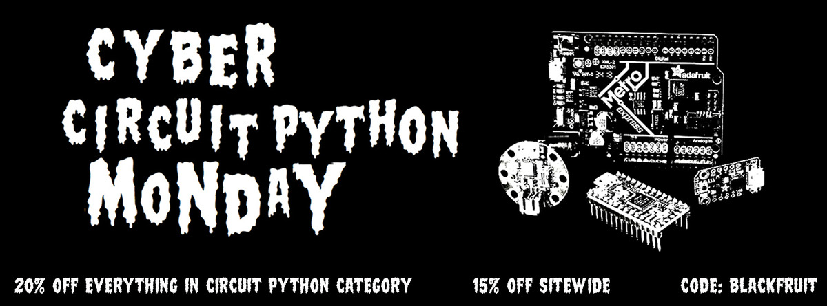
Our friends at Adafruit are also having a Cyber Monday sale, with 20% off on their CircuitPython product line and 15% off sitewide. See their blog post for more details!
Our Black Friday/Cyber Monday sale is going strong, and happy Thanksgiving from Romi Turkey

Our biggest sale of the year is underway, and manufacturing and shipping are working hard to make your robot parts and ship them out. You’ve done a fantastic job challenging them so far, but they’ve still managed to keep up with our same-day shipping guarantee, even though we have suspended that during the sale. Let’s keep up the pressure and challenge them even more as the sale goes on!
There will be no doorbusters this weekend, just great deals on lots of products all weekend long. Doorbusters will return Monday morning, the last day of the sale.
Now, for something else fun: in the spirit of Thanksgiving, we dressed a Romi robot up as a Turkey. Enjoy!
Our huge Black Friday/Cyber Monday sale is almost here!

Greetings and Happy Thanksgiving from Pololu! Our biggest sale of the year is almost here, and like last year, we are offering different deals and doorbusters every day, starting tomorrow and running through Cyber Monday. Most sale products will be available with free US shipping, which should make it easy for you to place multiple orders throughout the sale to get in on the different deals. All of the sale details along with Wednesday’s specials are up on the sale page now, and don’t forget that the Wednesday doorbusters start at 6 AM Pacific Time!
Be sure to check the sale page daily for new deals, and you can also sign up for our mailing list to receive sale updates and exclusive offers.
New RoboClaw and MCP motor controllers from Basicmicro
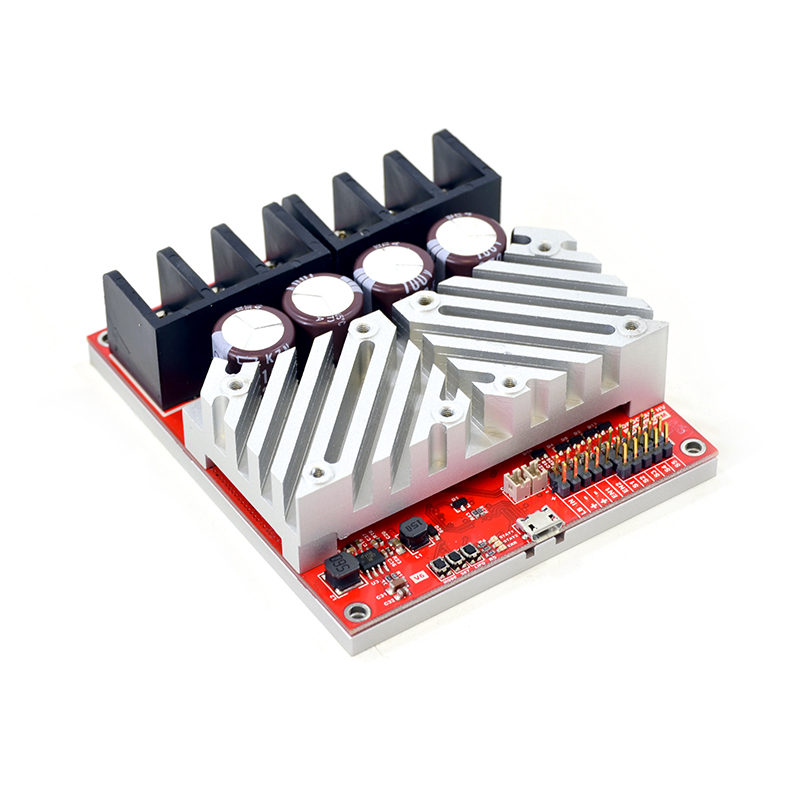 |
RoboClaw 2×60AHV, 60VDC Motor Controller. |
|---|
We are excited to offer eight new powerful motor controllers from Basicmicro (formerly Ion Motion Control):
- RoboClaw 2x60AHV, 60VDC
- RoboClaw 2x160A, 60VDC
- MCP233 Dual 30A, 34VDC
- MCP236 Dual 30A, 60VDC
- MCP263 Dual 60A, 34VDC
- MCP266 Dual 60A, 60VDC
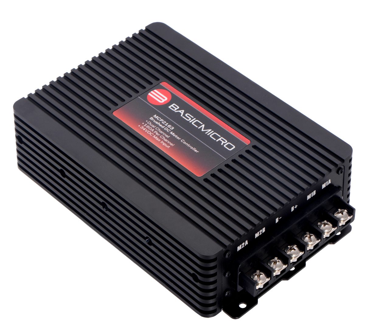
- MCP2163 Dual 160A, 34VDC
- MCP2166 Dual 160A, 60VDC
The two new RoboClaws bring our total selection of those to nine versions. Unlike the other RoboClaws, which have a maximum operating voltage of 34 V, these new RoboClaws and some of the new MCP controllers can work up to 60 V and deliver a continuous 60 A or 120 A per channel, making them the most powerful motor controllers we carry by far.
|
|
|
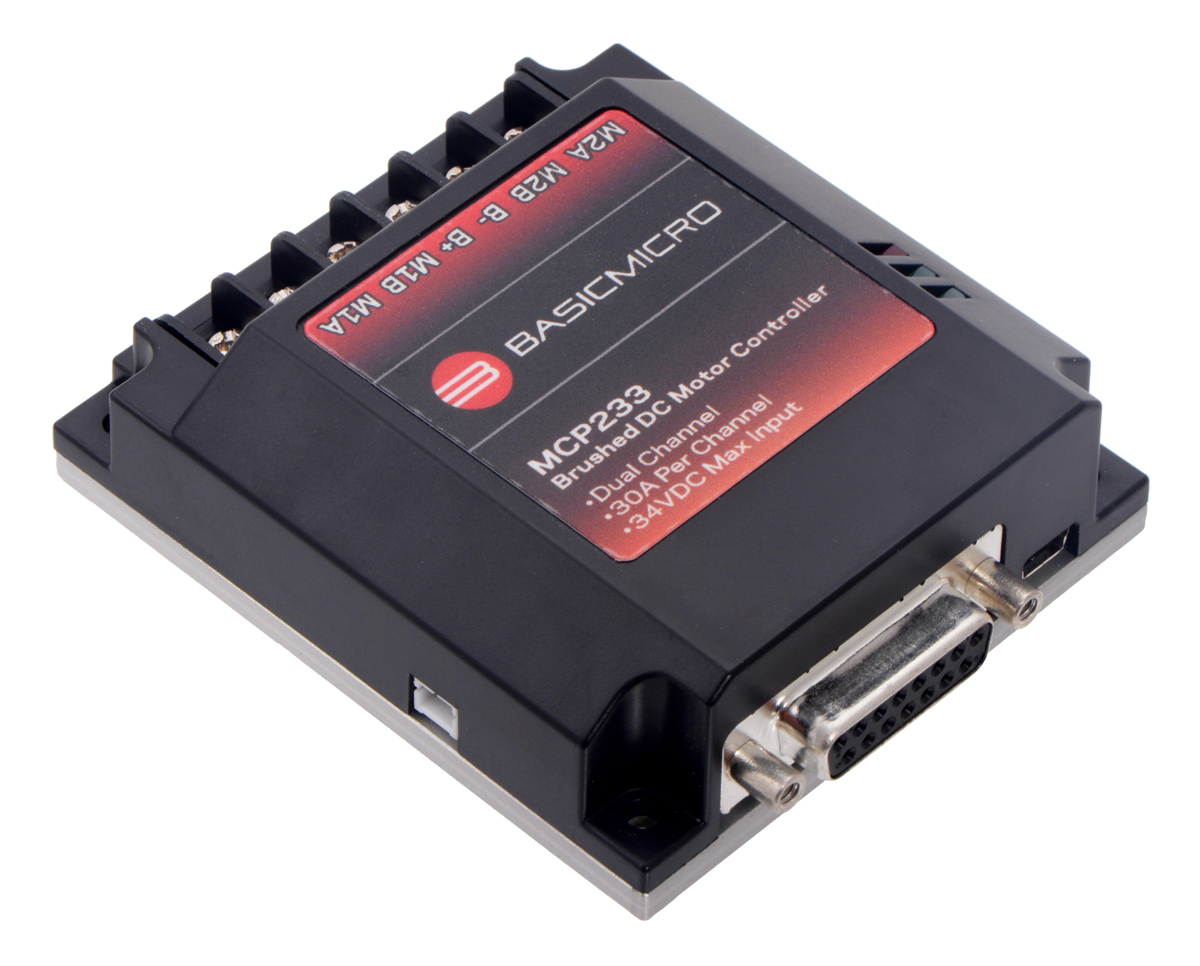
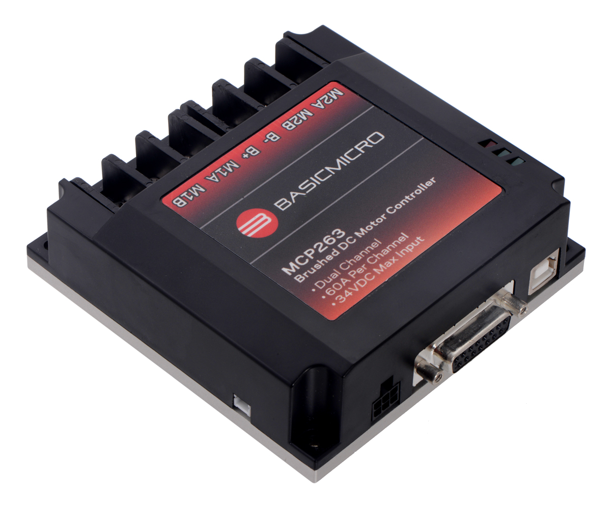
The six MCP products are from Basicmicro’s rugged new line of MCP Advanced Motor Controllers, which are optionally programmable via a built-in scripting language and support a variety of interfaces, including USB serial, TTL serial, RS-232 serial, CAN bus, RC hobby servo pulses, and analog voltages. Here is a summary of the key features of the MCP:
- Simple bidirectional control of two brushed DC motors
- 10–34 V or 10–60 V operating supply range, depending on controller model
- 30 A to 160 A maximum continuous current output, depending on controller model
- Channel bridging allows control of a single motor with double the current capability
- Automatic current limiting reduces duty cycle when temperature exceeds 85° C
- Six communication or control options:
- USB serial interface (virtual COM port)
- 3.3 V logic-level (TTL) serial interface for direct connection to microcontrollers or other embedded controllers
- RS-232 serial interface
- CAN bus interface supporting CANopen protocol as master or slave device
- Hobby radio control (RC) pulse width interface for direct connection to an RC receiver or RC servo controller
- Analog voltage (0 V to 5 V) interface for direct connection to potentiometers and analog joysticks
- Automatic control switching with user-defined priority settings
- I²C interface accessible by user script
- Up to 20 user-defined input pins for control, feedback, or scripting, depending on controller model
- All inputs are 15 V tolerant for interfacing to industrial devices such as PLCs
- Up to 8 user-defined open-drain output pins (40 V max) for driving auxiliary loads, depending on controller model
- Multiple feedback options for PID closed-loop control:
- Speed or position control with quadrature encoders, up to 21 million encoder pulses per second
- Position control with analog encoders or potentiometers
- (Open-loop control with no feedback also available)
- Programmable with built-in user scripting language
- Screw terminals for quick connect/disconnect
- Configurable via USB connection and PC software
- Regenerative braking
- Tolerates high-speed direction changes
- 5 V BEC can power external logic
- Battery monitoring and under-voltage cutoff protects batteries from over-discharging
- Fully enclosed for protection
- Conduction plate for cooling on bottom of enclosure
Related products


New products: TB67S249FTG and TB67S279FTG Stepper Motor Driver Compact Carriers
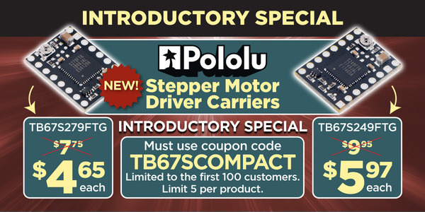
Earlier this week, we released new compact carriers for Toshiba’s great stepper motor drivers, the TB67S249FTG and TB67S279FTG. We released larger carrier boards for those two chips in the summer, and those are still the version to get if you want to test all the features that those ICs offer. The new compact carriers are in our popular 16-pin, 0.6″ × 0.8″ form factor (which I originally designed for the Allegro A4983 back in 2009 when I was still routing most of our circuit boards), making it easy to use the new drivers on RAMPS-type 3D printer controllers that have the compatible sockets.
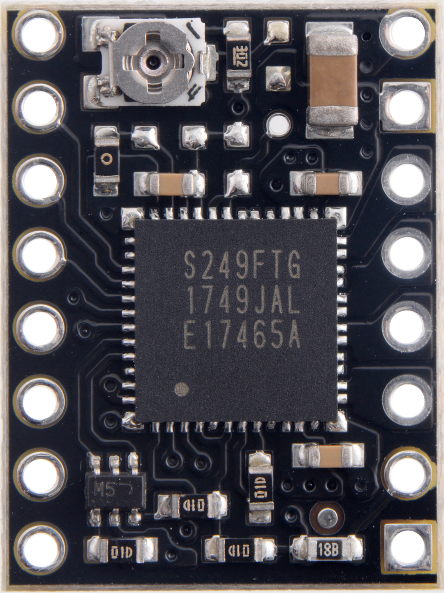
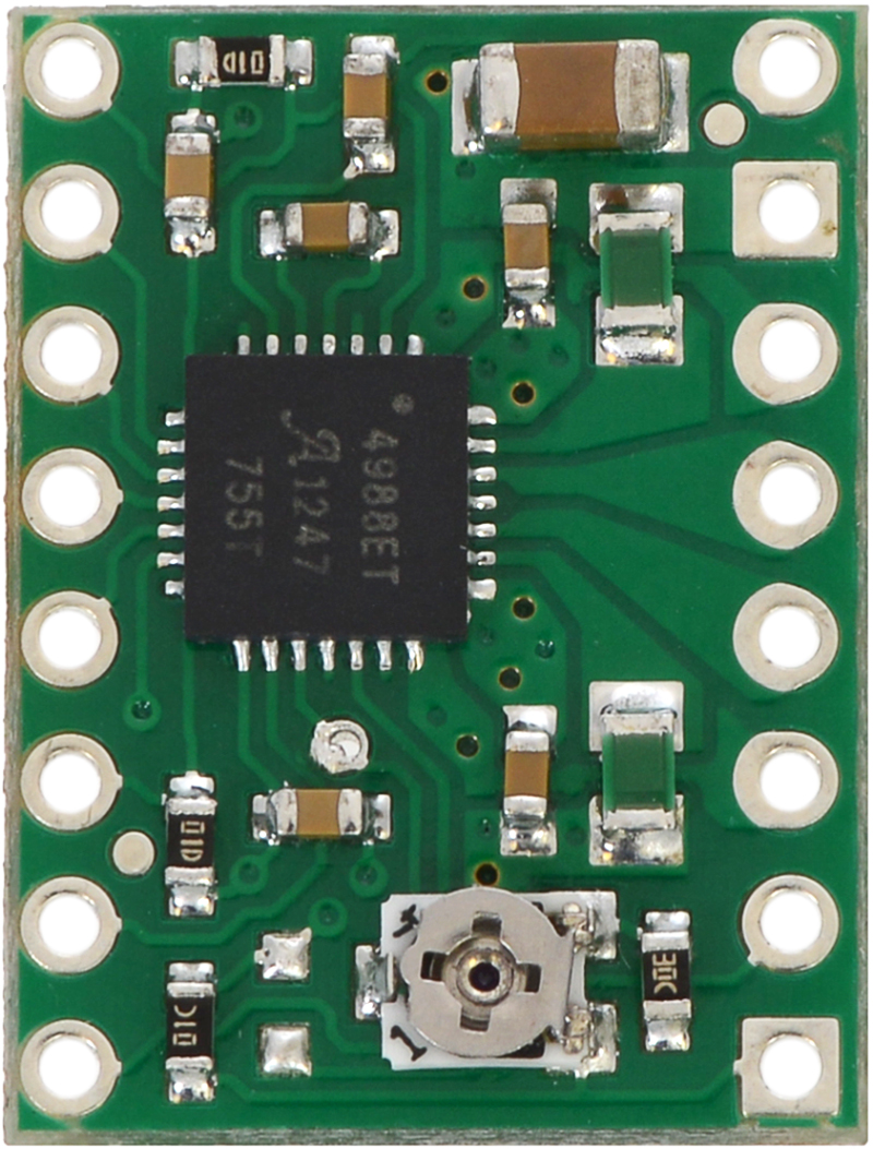
These Toshiba chips are massive, and you can see how much more space they take up on that common PCB size when compared to the original board (populated with the Allegro A4988 that replaced the A4983):
|
|
In addition to fitting the larger chip onto the same board space, we had to add some external inverters to make the enable and reset lines behave the same way as on the original modules (this schematic is also available as a downloadable pdf (141k pdf)).
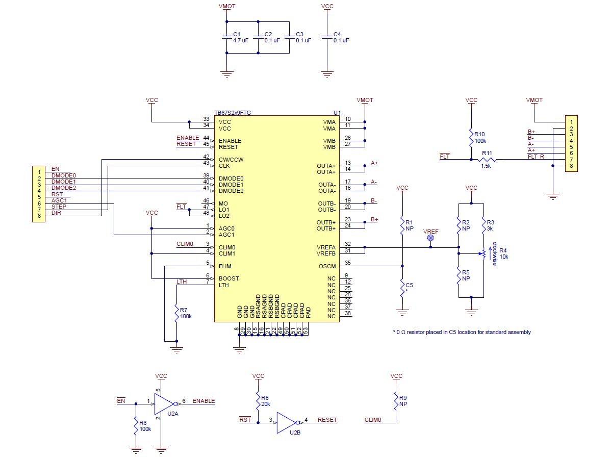 |
Schematic diagram of the TB67S249FTG/TB67S279FTG Stepper Motor Driver Compact Carrier. |
|---|
We also had to hardwire many of the options that the TB67Sx49FTG chips offer. In particular, we set the Active Gain Control (AGC) lower current limit to 60%. This innovative feature on the Toshiba stepper drivers allows the current through the stepper motor to be reduced based on what the motor actually needs, which allows for reduced unnecessary heat generation in the motor and higher peak power when you actually need it. I have heard (from Toshiba’s competitors, who also acknowledged that Toshiba is one of the few big semiconductor companies bringing real innovation to stepper motor drivers) of the AGC feature not working in some applications, but when it works, it’s quite amazing. We tried out the Toshiba TB67S249FTG drivers on a Tevo Tornado 3D printer that originally had Allegro A4988 drivers on an MKS GEN control board, and we could run at higher current and with 1/32 microstepping instead of the A4988’s 1/16 microstepping, which also gave a noticeable improvement in print quality.
The TB67S249FTG is now our highest-power option, and in addition to delivering a little bit more power than our previous leader, the TI DRV8825, the Toshiba driver seems to provide better current control with the relatively low inductance, low resistance coils often used on these low-end 3D printers. If you do not need that maximum current aspect, you can get all the other special features with the lower-power, lower-cost TB67S279FTG.
As with all of our new products this year, we are offering an introductory special. For these two new modules, we are offering 40% off for up to five units (per version!) to the first 100 customers that use coupon code TB67SCOMPACT. This means you can try out the top-of-the-line TB67S249FTG for less than $6.
Related products


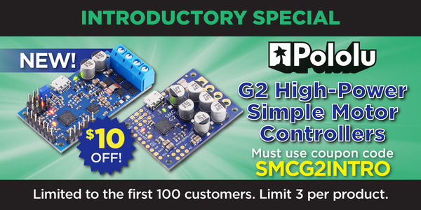
New G2 Simple Motor Controllers
Last week, we released updated (G2) versions of our Simple Motor Controllers. We released our original Simple Motor Controllers just over eight years ago as our most economical basic motor controllers for brushed DC motors using up to a few hundred watts. The “simple” in the name came from our trying to have fun with all the requests we had from our customers, many of whom wanted “just” this one feature. Of course, everyone wants a different feature in their minimal motor controller, so the Simple Motor Controllers actually have quite a few options, but we make it easy to set up with configuration over USB.
|
|

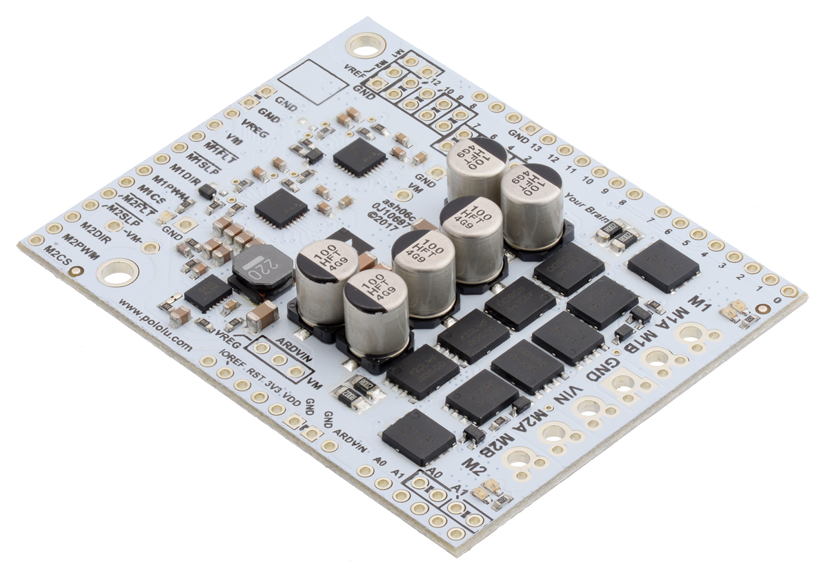 |
Pololu Dual G2 High-Power Motor Driver 24v18 Shield for Arduino. |
|---|
Over the last few years, we have been updating our higher-power motor drivers (H-bridges with external MOSFETs) to use newer MOSFETs and MOSFET drivers, and we refer to them as our G2 high-power motor drivers. These drivers are available as small, single-channel boards, as well as dual drivers in Arduino shield and Raspberry Pi HAT form factors. Earlier this year, we brought the improved motor drivers to our Jrk G2 Motor Controllers with Feedback for those wanting to make their own closed-loop servo systems.
Now, the G2 motor driver technology is available on our Simple Motor Controllers as well. For the most part, this is not as big of a change as with the other G2 motor control products, but we did add a few nice features while maximizing backward compatibility. Key improvements over the originals include reverse voltage protection, configurable hardware current limiting, and the addition of an I²C interface for yet another control option—the others being USB, analog voltage, hobby RC servo interface, and asynchronous serial (UART). Additionally, the highest-power units (the SMC G2 18v25 and 24v19) use a four-layer board with double-sided assembly, which lets them be much smaller than their original SMC 18v25 and 24v23 counterparts:
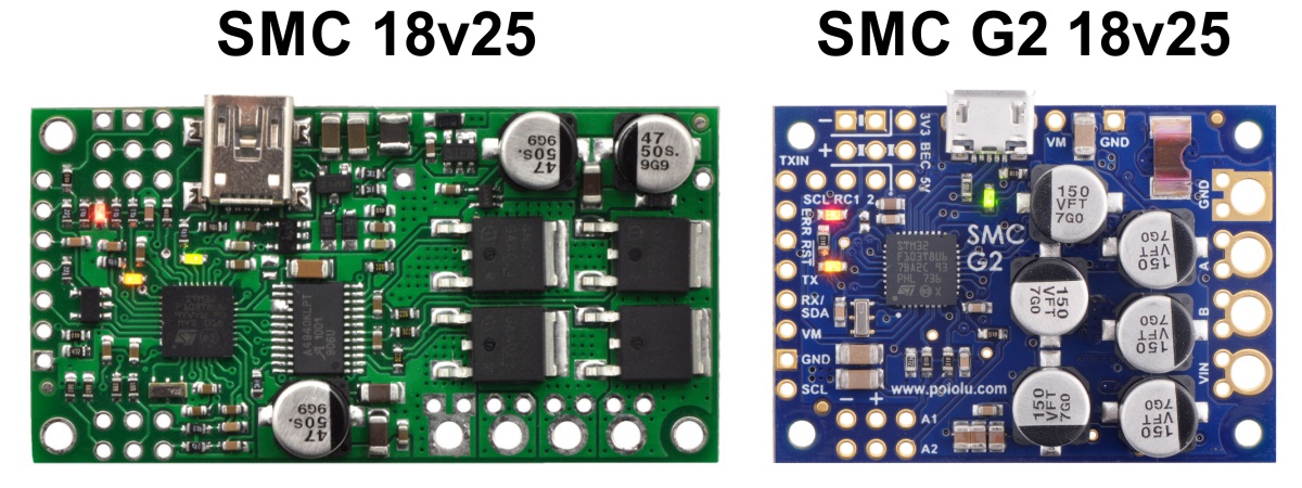 |
Side-by-side comparison of the original SMC 18v25 and the newer SMC G2 18v25. |
|---|
The lower-power units have the exact same size and generally have the same connector locations as the original Simple Motor Controllers:
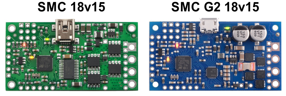 |
Side-by-side comparison of the original SMC 18v15 and the newer SMC G2 18v15. |
|---|
The most notable difference from a form factor and connection standpoint is the change from the USB mini-B connector on the older motor controllers to the micro-B connector on the G2 models. The following table shows the main specifications of all of the old and new Simple Motor Controllers:
| Original versions, not recommended for new designs (included for comparison purposes) |
G2 versions, released November 2018 |
|||||||||
 SMC 18v7 |
 SMC 18v15 |
SMC 24v12 |
 SMC 18v25 |
SMC 24v23 |
 SMC G2 18v15 |
 SMC G2 24v12 |
 SMC G2 18v25 |
 SMC G2 24v19 |
||
|---|---|---|---|---|---|---|---|---|---|---|
| Minimum operating voltage: | 5.5 V | 5.5 V | 5.5 V | 5.5 V | 5.5 V | 6.5 V | 6.5 V | 6.5 V | 6.5 V | |
| Recommended max operating voltage: |
24 V(1) | 24 V(1) | 34 V(2) | 24 V(1) | 34 V(2) | 24 V(1) | 34 V(2) | 24 V(1) | 34 V(2) | |
| Max nominal battery voltage: |
18 V | 18 V | 28 V | 18 V | 28 V | 18 V | 28 V | 18 V | 28 V | |
| Max continuous current (no additional cooling): |
7 A | 15 A | 12 A | 25 A | 23 A | 15 A | 12 A | 25 A | 19 A | |
| USB, TTL serial, Analog, RC control: |
 |
|
|
|
|
|
|
|
|
|
| I²C control: | |
|
|
|
||||||
| Hardware current limiting: | |
|
|
|
||||||
| Reverse voltage protection: | |
|
|
|
||||||
| Dimensions: | 2.1″ × 1.1″ | 2.3″ × 1.2″ | 2.1″ × 1.1″ | 1.7″ × 1.2″ | ||||||
| Price: | $157.53 | $161.27 | $169.88 | $201.99 | $204.14 | $135.02 | “”price">$135.02":$135.02 | “”price">$165.09":$165.09 | “”price">$165.09":$165.09 | |
| Available with connectors installed? |
Yes | Yes | Yes | No | No | Yes | Yes | No | No | |
| 1 30 V absolute max. 2 40 V absolute max. |
||||||||||
Key features of the SMC G2 family
- Simple bidirectional control of one brushed DC motor
- Five communication or control options:
- USB interface for direct connection to a PC
- Logic-level (TTL) serial interface for use with a microcontroller
- I²C interface for use with a microcontroller
- Hobby radio control (RC) pulse width interface for direct connection to an RC receiver or RC servo controller
- 0 V to 3.3 V analog voltage interface for direct connection to potentiometers and analog joysticks
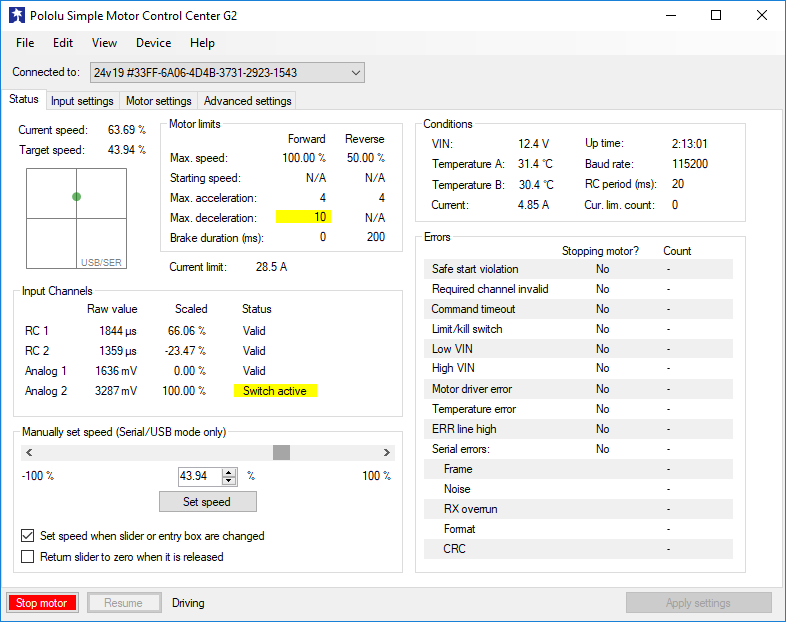
- Simple configuration and calibration over USB with a free configuration program for Windows
- Reverse-voltage protection
- Hardware current limiting with a configurable threshold
- Current sensing
Note: A USB A to Micro-B cable (not included) is required to connect this controller to a computer.
Additional features of the SMC G2 family
- Adjustable maximum acceleration and deceleration to limit electrical and mechanical stress on the system
- Adjustable starting speed and maximum speed
- Option to brake or coast when speed is zero
- Optional safety controls to avoid unexpectedly powering the motor
- Input calibration (learning) and adjustable scaling degree for analog and RC signals
- Under-voltage shutoff with hysteresis for use with batteries vulnerable to over-discharging (e.g. LiPo cells)
- Adjustable over-temperature threshold and response
- Adjustable PWM frequency from 1.13 kHz to 22.5 kHz (maximum frequency is ultrasonic, eliminating switching-induced audible motor shaft vibration)
- Error LED linked to a digital ERR output, and connecting the error outputs of multiple controllers together optionally causes all connected controllers to shut down when any one of them experiences an error
- Field-upgradeable firmware
- Features of the serial, I²C, and USB interfaces:
- Optional CRC error detection to eliminate communication errors caused by noise or software faults
- Optional command timeout (shut off motors if communication ceases)
- Serial features:
- Controllable from a computer via serial commands sent to the device’s USB virtual serial (COM) port, or via TTL serial through the device’s RX/TX pins
- TTL serial uses 0 V and 3.3 V on TX, accepts 0 V to 5 V on RX
- Supports automatic baud rate detection from 1200 bps to 500 kbps, or can be configured to run at a fixed baud rate
- Supports standard compact and Pololu protocols as well as the Scott Edwards Mini SSC protocol and an ASCII protocol for simple serial control from a terminal program
- Optional serial response delay for communicating with half-duplex controllers such as the Basic Stamp
- Controllers can be easily chained together and to other Pololu serial motor and servo controllers to control hundreds of motors using a single serial line
- I²C features:
- Compatible with I²C bus voltage levels from 1.8 V to 5 V
- USB features:
- Full-speed USB interface (12 Mbps)
- Example code in C#, Visual Basic .NET, and Visual C++ is available in the Pololu USB Software Development Kit
- RC features:
- 1/4 µs pulse measurement resolution
- Works with RC pulse frequencies from 10 to 333 Hz
- Configurable parameters for determining what constitutes an acceptable RC signal
- Two RC channels allow for single-stick (mixed) motor control, making it easy to use two Simple Motor Controllers in tandem on an RC-controlled differential-drive robot
- RC channels can be used in any mode as limit or kill switches (e.g. use an RC receiver to trigger a kill switch on your autonomous robot)
- Battery elimination circuit (BEC) jumper can power the RC receiver with 5 V or 3.3 V
- Analog features:
- 0.8 mV (12-bit) measurement resolution
- Works with 0 to 3.3 V inputs
- Optional potentiometer/joystick disconnect detection
- Two analog channels allow for single-stick (mixed) motor control, making it easy to use two Simple Motor Controllers in tandem on a joystick-controlled differential-drive robot
- Analog channels can be used in any mode as limit or kill switches
As with all of our new products this year, we are offering an introductory special. Be among the first 100 customers to use coupon code SMCG2INTRO and get $10 off on up to three units (per version)!
Related products


New Pololu circuit logo T-Shirts!
 |
Our new circuit logo T-shirts are here! They feature the Pololu logo, composed of a white printed circuit board (PCB) layout, on the front and the phrase “Engage Your Brain” on the back. These pre-shrunk cotton shirts are available in several colors (black, sapphire blue, or cardinal red) and a range of youth and adult sizes.
|
|
|


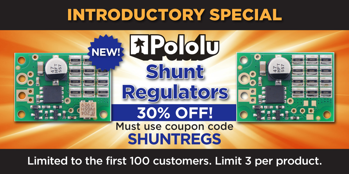
New products: Shunt Regulators
 |
When I think of a robot, I usually picture a mobile robot, which generally means it is powered by a battery. Most of our motor controller products are built with that kind of bias in mind, too. But there are obviously many permanent installations that still call for motion, from 3D printers and robot arms to kinetic sculptures and motion simulators. And powering those can be complicated and expensive, with power supplies capable of powering bigger motors often costing more than the motors and the motor controllers. One difficulty is that power supplies are often not particularly good for absorbing the little pulses of power that motors and motor controllers sometimes send back out (typically when a motor is slowing down). The ramifications can be very bad since the supply voltages can quickly get destructively high when the current has nowhere to go. Many better power supplies have over-voltage protection, but that just means the power supply shuts down. While that’s better than expensive parts going up in smoke, it can still keep your project from functioning.
The simplest solution to the problem is often a transient voltage suppressor, or TVS, which is a big zener diode optimized for handling big current spikes. Unfortunately, TVS diodes typically do not have a tight enough tolerance for use with power supplies with over-voltage protection. For example, a 12V power supply might have 5% tolerance, meaning the output voltage could be as high as 12.6V, so the protection device must not kick in below 12.6V. If the over-voltage protection is triggered by a 15% deviation, any voltage spikes must be kept below 13.8V. Most basic TVSes do not have tight enough tolerances to ensure operation in that window.
So, we developed a shunt regulator that should help with that kind of scenario. A simplified schematic diagram of the shunt regulator is shown below. Basically, a circuit monitors the voltage and controls a MOSFET that allows current to flow through a shunt resistance that sets the maximum current the device can sink.
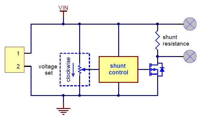 |
Simplified schematic diagram of the Shunt Regulators. |
|---|
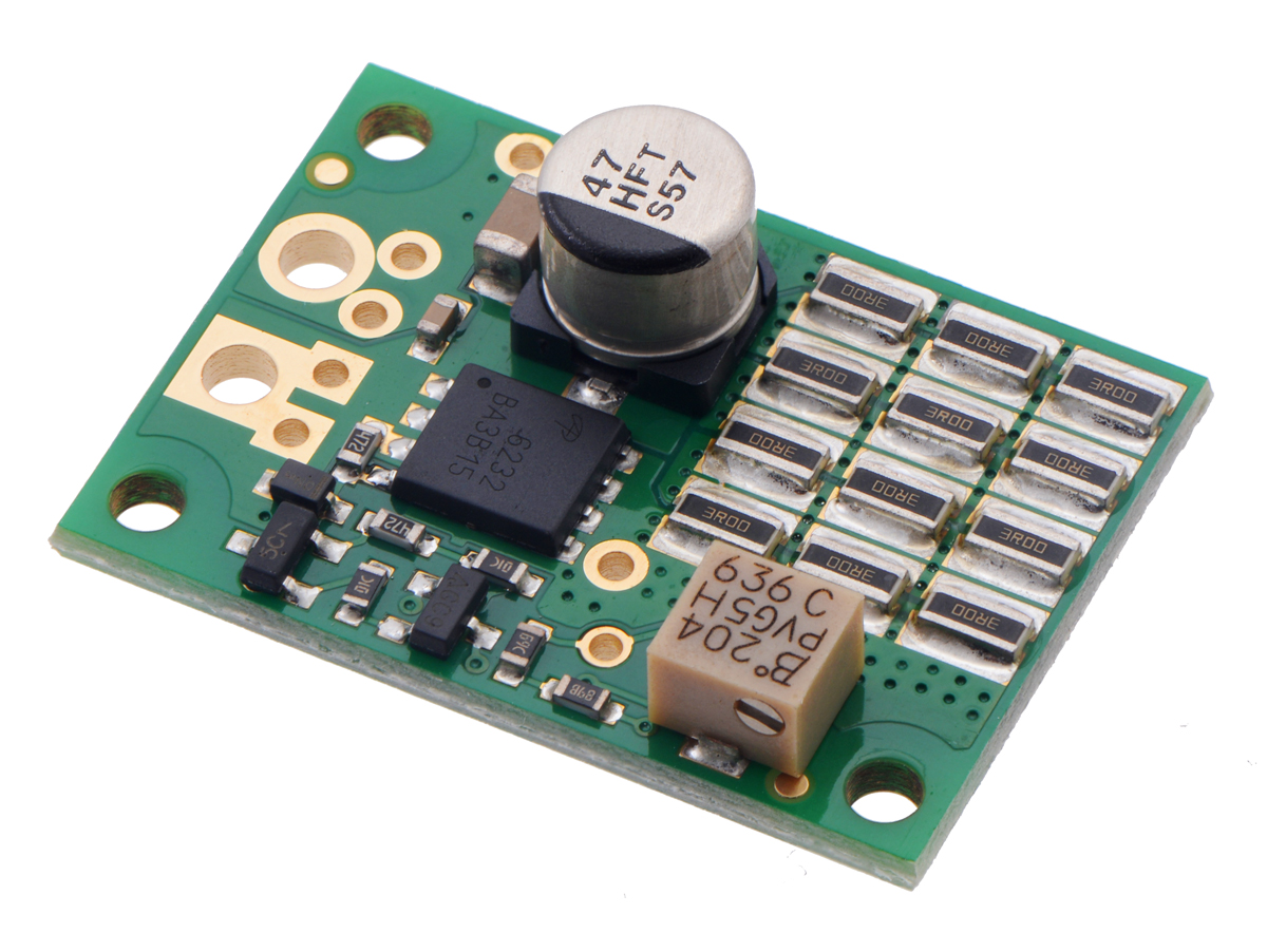
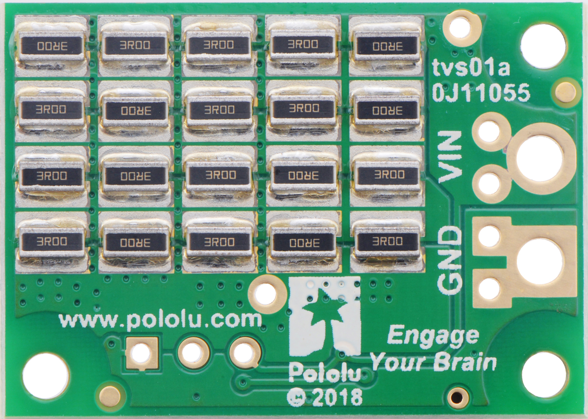
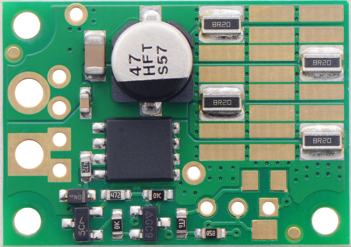
We offer the shunt regulators with a variety of voltage set points and shunt resistances. Available variations include fixed resistances and multi-turn potentiometers for the voltage set point, different shunt resistances for the load, and different power ratings for the shunt resistance (the higher-power versions have twenty more resistors populated on the back side of the board).
|
|
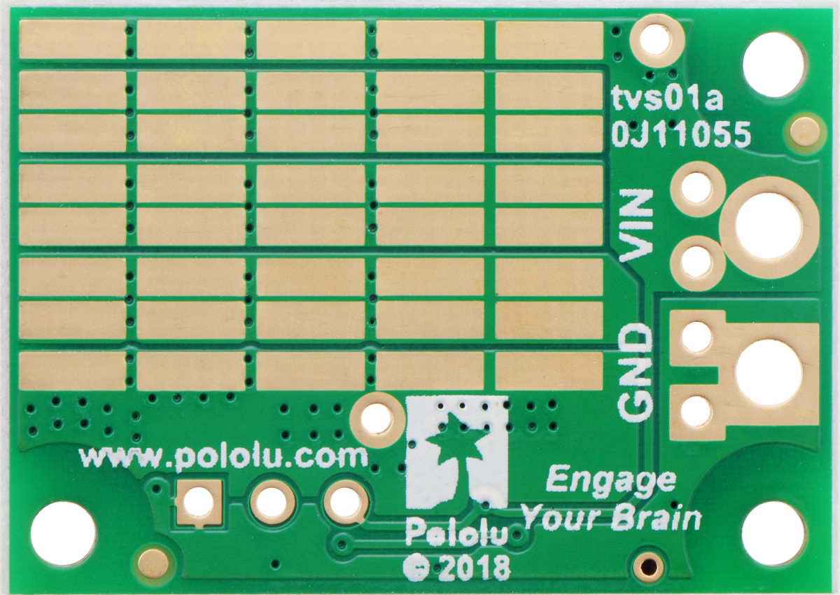
One version of the shunt regulator is populated with an especially high shunt resistance with minimal power rating; this unit is intended for use with an external shunt resistance:
 |
Shunt Regulator: 33.0 V, 32.8Ω, 3W. |
|---|
The available versions are shown in the table below:
| Voltage | ||||||
|---|---|---|---|---|---|---|
| 13.2 V | 26.4 V | 33.0 V | Fine-adjust LV | Fine-adjust HV | ||
| Power | 3 W | – | – | #3780 32.8 Ω |
– | – |
| 9 W | #3770 1.33 Ω |
#3774 4.00 Ω |
#3776 4.00 Ω |
– | – | |
| 15 W | #3771 1.50 Ω |
#3775 2.80 Ω |
#3777 4.10 Ω |
#3778 1.50 Ω |
#3779 4.10 Ω |
|
This product is more for advanced users at this point since it can be difficult to determine how much power your motor is dumping back onto the power supply, but since we have the products working and several customers waiting to use them, we are going ahead with releasing them. We expect to develop additional resources and to put up verified regulator/motor controller combinations over time.
The basic regulators are quite inexpensive, and we are offering an introductory special as we are with all new products this year, so you might want to pick some up to play around with. The first hundred customers to use coupon code SHUNTREGS get 30% off on up to three units (per version).
Related products


Home | Forum | Blog | Support | Ordering Information | Lists | Distributors | BIG Order Form | About | Contact
© 2001–2026 Pololu Corporation


