Pololu Blog » Engage Your Brain »
New products: Shunt Regulators
 |
When I think of a robot, I usually picture a mobile robot, which generally means it is powered by a battery. Most of our motor controller products are built with that kind of bias in mind, too. But there are obviously many permanent installations that still call for motion, from 3D printers and robot arms to kinetic sculptures and motion simulators. And powering those can be complicated and expensive, with power supplies capable of powering bigger motors often costing more than the motors and the motor controllers. One difficulty is that power supplies are often not particularly good for absorbing the little pulses of power that motors and motor controllers sometimes send back out (typically when a motor is slowing down). The ramifications can be very bad since the supply voltages can quickly get destructively high when the current has nowhere to go. Many better power supplies have over-voltage protection, but that just means the power supply shuts down. While that’s better than expensive parts going up in smoke, it can still keep your project from functioning.
The simplest solution to the problem is often a transient voltage suppressor, or TVS, which is a big zener diode optimized for handling big current spikes. Unfortunately, TVS diodes typically do not have a tight enough tolerance for use with power supplies with over-voltage protection. For example, a 12V power supply might have 5% tolerance, meaning the output voltage could be as high as 12.6V, so the protection device must not kick in below 12.6V. If the over-voltage protection is triggered by a 15% deviation, any voltage spikes must be kept below 13.8V. Most basic TVSes do not have tight enough tolerances to ensure operation in that window.
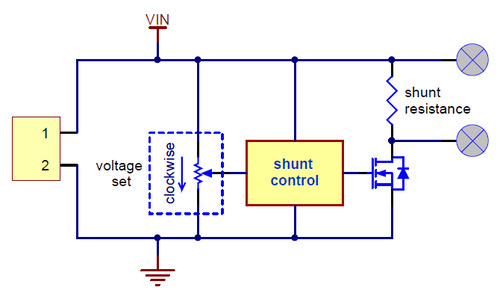
So, we developed a shunt regulator that should help with that kind of scenario. A simplified schematic diagram of the shunt regulator is shown below. Basically, a circuit monitors the voltage and controls a MOSFET that allows current to flow through a shunt resistance that sets the maximum current the device can sink.
 |
Simplified schematic diagram of the Shunt Regulators. |
|---|
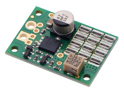
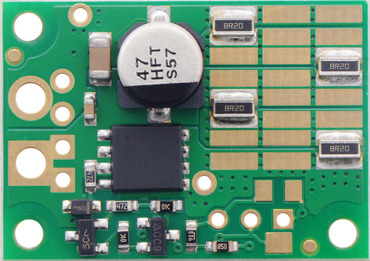
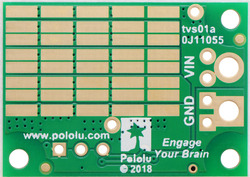
We offer the shunt regulators with a variety of voltage set points and shunt resistances. Available variations include fixed resistances and multi-turn potentiometers for the voltage set point, different shunt resistances for the load, and different power ratings for the shunt resistance (the higher-power versions have twenty more resistors populated on the back side of the board).
|
|
One version of the shunt regulator is populated with an especially high shunt resistance with minimal power rating; this unit is intended for use with an external shunt resistance:
 |
Shunt Regulator: 33.0 V, 32.8Ω, 3W. |
|---|
The available versions are shown in the table below:
| Voltage | ||||||
|---|---|---|---|---|---|---|
| 13.2 V | 26.4 V | 33.0 V | Fine-adjust LV | Fine-adjust HV | ||
| Power | 3 W | – | – | #3780 32.8 Ω |
– | – |
| 9 W | #3770 1.33 Ω |
#3774 4.00 Ω |
#3776 4.00 Ω |
– | – | |
| 15 W | #3771 1.50 Ω |
#3775 2.80 Ω |
#3777 4.10 Ω |
#3778 1.50 Ω |
#3779 4.10 Ω |
|
This product is more for advanced users at this point since it can be difficult to determine how much power your motor is dumping back onto the power supply, but since we have the products working and several customers waiting to use them, we are going ahead with releasing them. We expect to develop additional resources and to put up verified regulator/motor controller combinations over time.
The basic regulators are quite inexpensive, and we are offering an introductory special as we are with all new products this year, so you might want to pick some up to play around with. The first hundred customers to use coupon code SHUNTREGS get 30% off on up to three units (per version).
7 comments
The shunt resistances are already optimized for the power level and voltage of the available models. You can see in the simplified schematic that the resistors set the maximum current that the shunt regulator will draw for a given voltage, and that's just an Ohm's Law V=IR case. So if you make them too big for a given expected voltage, the regulator might not be able to draw enough current to keep the voltage from spiking. On the flip side, making the resistors too small is a power dissipation issue, where that power is V^2/R. So you have to make sure that for the resistance and voltage you expect, you will not exceed the power the resistors can dissipate.
-Claire
The MOSFET also dissipates power and can be a limiting component, and it can depend a lot on your application how the power gets split between the resistors and MOSFET. Please keep in mind, the power ratings are intended primarily to indicate the relative average power-handling capabilities of the boards for up to a few seconds. The boards are designed for clamping occasional short (up to tens of ms) higher power pulses.
If you contact us with more details about what you want to do, we might be able to offer more specific feedback.
- Patrick
We do not recommend using them in parallel since they are not guaranteed to split the load separately.
- Brandon


