Pololu Blog »
Pololu Blog (Page 17)
Welcome to the Pololu Blog, where we provide updates about what we and our customers are doing and thinking about. This blog used to be Pololu president Jan Malášek’s Engage Your Brain blog; you can view just those posts here.
Popular tags: community projects new products raspberry pi arduino more…
TI Robotics System Learning Kit (TI-RSLK) in EDN’s hot 100 products of 2018
|
|


EDN recently released their hot 100 products of 2018, and we are excited to share that the TI Robotics System Learning Kit (TI-RSLK), which is based on our Romi platform, is included in the list. For those not familar with the TI-RSLK, it is a complete robotics kit and curriculum aimed at university students. Twenty modules with lecture notes, lab activities, and over a hundred videos are all publicly available.
The kit was included in the Tools & Development section of the list, and you can read EDN’s review of the kit from earlier in the year here. Kits can be purchased from Element14.
New Tic T500 revision to address problem with missed steps
One of the fun things you learn as an engineer is that physically laying out a circuit requires a lot more than simply confirming it matches the schematic. In practice, there are many more things to think about, and if you’ve seen datasheets with layout guidelines or recommendations, you’re probably aware of some of them. (Thermal considerations, adequate decoupling, minimizing parasitic inductance and capacitance…) What’s more, these considerations are often in conflict (e.g. is it better to have the decoupling capacitor closer to the IC or to have a wider trace for that high-current path?), and trouble can arise if you don’t correctly assess their relative importance. That is what happened to us with our Tic T500 stepper motor controller, where the location of a specific decoupling capacitor ended up being far more significant than we had anticipated. Continued…
New product: STSPIN220 Low-Voltage Stepper Motor Driver Carrier with 1/256 microstepping
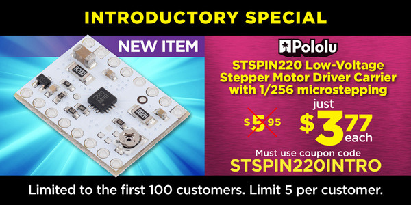
I am happy to announce our first new product of 2019, a carrier board for the STSPIN220 stepper motor driver, which operates all the way down to 1.8 V, making it our lowest-voltage stepper motor driver. And like its higher-voltage sibling, the STSPIN820 that we released a few months ago, it offers microstepping down to 1/256 steps. This new carrier board has the same 16-pin, 0.6″ × 0.8″ form factor as our other popular stepper motor drivers, and as with our STSPIN820 carrier, it inverts the enable input so that it has the more familiar functionality of those drivers (but be careful not to pop these into a 12 V or 24 V socket!).
By the way, keep in mind that you do not necessarily need a low-voltage stepper motor driver just because your stepper motor has a low rated voltage. The voltage rating is just the voltage at which your stepper motor will draw its rated current, and it’s really the current rating that you need to be careful about if you want to avoid damaging your stepper motor. All of our stepper motor drivers let you limit the maximum current, so as long as you set the limit below the rated current, you will be within spec for your motor, even if the voltage exceeds the rated voltage. In general, using a high supply voltage along with active current limiting allows for better performance, so the main reason for using a low-voltage stepper motor driver like the STSPIN220 is if your supply voltage is constrained to some low value by some other aspect of your system.
This new release brings our selection of stepper motor drivers in this compact form factor to eleven:
 A4988 (original) |
 A4988, Black Ed. |
 DRV8825 |
 DRV8834 |
 DRV8880 |
 MP6500, Pot. CC |
 MP6500, Digital CC |
 TB67S279FTG |
 TB67S249FTG |
 STSPIN820 |
 STSPIN220 |
|
|---|---|---|---|---|---|---|---|---|---|---|---|
| Driver chip: | A4988 | DRV8825 | DRV8834 | DRV8880 | MP6500 | TB67S279FTG | TB67S249FTG | STSPIN820 | STSPIN220 | ||
| Min operating voltage: | 8 V | 8.2 V | 2.5 V | 6.5 V | 4.5 V | 10 V | 10 V | 7 V | 1.8 V | ||
| Max operating voltage: | 35 V | 45 V | 10.8 V | 45 V | 35 V | 47 V | 47 V | 45 V | 10 V | ||
| Max continuous current per phase:(1) | 1 A | 1.2 A | 1.5 A | 1.5 A | 1 A | 1.5 A | 1.1 A | 1.6 A | 0.9 A | 1.1 A | |
| Peak current per phase:(2) | 2 A | 2.2 A | 2 A | 1.6 A | 2.5 A | 2 A | 2 A | 4.5 A | 1.5 A | 1.3 A | |
| Microstepping down to: | 1/16 | 1/32 | 1/32 | 1/16 | 1/8 | 1/32 | 1/32 | 1/256 | 1/256 | ||
| Board layer count: | 2 | 4 | 4 | 4 | 4 | 4 | 4 | 4 | 4 | 4 | |
| Special features: | high current | low-voltage operation, high current |
AutoTune, digital current reduction |
high current | digital current control, high current |
Auto Gain Control, ADMD, high max voltage |
Auto Gain Control, ADMD, high max voltage, high current |
128 and 256 microsteps, high max voltage |
64, 128, and 256 microsteps, low-voltage operation |
||
| 1-piece price: | $8.95 | $9.95 | $15.95 | $9.95 | $8.95 | $9.95 | $9.95 | $11.75 | $13.95 | $18.95 | $10.95 |
| 1 On Pololu carrier board, at room temperature, and without additional cooling. 2 Maximum theoretical current based on components on the board (additional cooling required). |
|||||||||||
Last year, we began offering introductory specials to celebrate each newly released product, and we are continuing with that this year: the first 100 customers that use coupon code STSPIN220INTRO can get up to five units at just $3.77 each.
Related products


Balboa controlled via cell phone over Bluetooth
Drew Wilkerson added a Robotis BT-410 Bluetooth-to-serial board to his Balboa Robot, which allows him to control that Balboa from a cell phone. You can watch the video above to see the Balboa being driven around as it balances. More information about this project, including the code running on Drew’s Balboa, can be found in his post on our forum.
Related products

Video: Easy Acrylic Unmasking
We do a lot of laser cutting here at Pololu as part of our custom laser-cutting service, so we know first hand how tedious it can be to remove the paper masking from laser cut parts like acrylic. Check out the video below for a simple trick you can use to speed up the process.
Related products

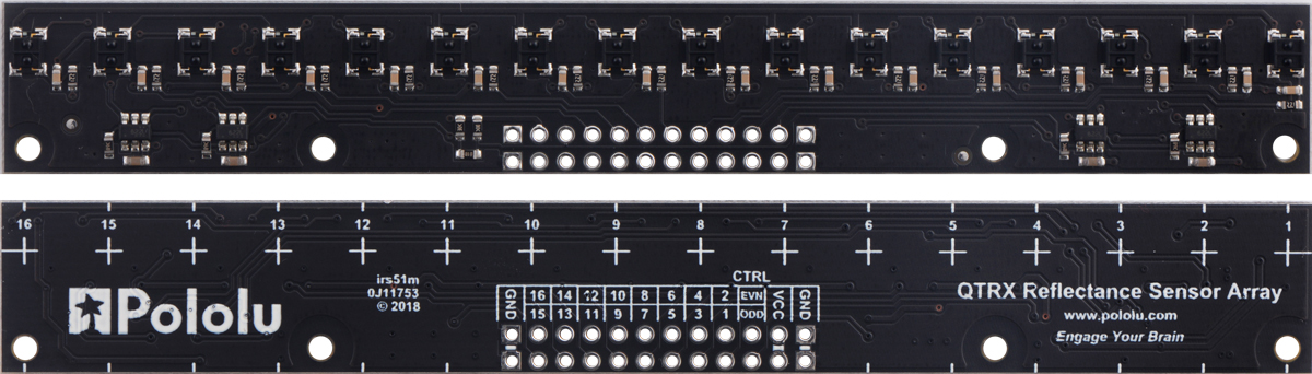
New products: 16-channel QTR MD reflectance sensor arrays
 |
 |
QTR-MD-16A Reflectance Sensor Array. |
|---|
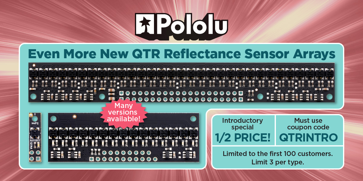
We now have 16-sensor, medium-density (8mm-pitch) versions of our new QTR reflectance sensor arrays. Like the versions already released, these new modules are available in analog and RC configurations and with two different sensor types, resulting in four new products in all:
- QTR-MD-16RC Reflectance Sensor Array
- QTR-MD-16A Reflectance Sensor Array
- QTRX-MD-16RC Reflectance Sensor Array
- QTRX-MD-16A Reflectance Sensor Array
Unlike the medium-density (MD) arrays we have released previously, which just use the high-density PCBs in partially populated configurations, these new 16-channel modules use PCBs specifically designed for an 8 mm pitch. As a result, these are the first MD versions that allow separate control of the odd and even emitters, which gives you extra options for detecting light reflected at various angles. They have the same board dimensions (125 × 16.5 mm) and mounting hole locations as the high-density (4mm-pitch) 31-channel arrays, but the pinout is different.
 |
QTR-MD-16A Reflectance Sensor Array. |
|---|
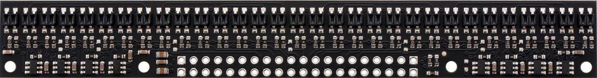 |
QTR-HD-31A Reflectance Sensor Array. |
|---|
For more information on our new QTR sensor family, you can see some of our previous blog posts about the versions we have already released:
- New products: 1- and 31-channel QTR HD reflectance sensor arrays
- New products: more new QTR HD sensor arrays by student engineering interns
- New products: QTR HD sensor arrays by student engineering interns
- New product: high-density QTR reflectance sensor arrays
Don’t forget to get in on our QTR introductory promotion! Be one of the first 100 customers to use coupon code QTRINTRO and get any of these new sensors at half price! (Limit 3 per item per customer.)
Related products


New product: 5-Channel Reflectance Sensor Array for Balboa 32U4 Balancing Robot
|
|
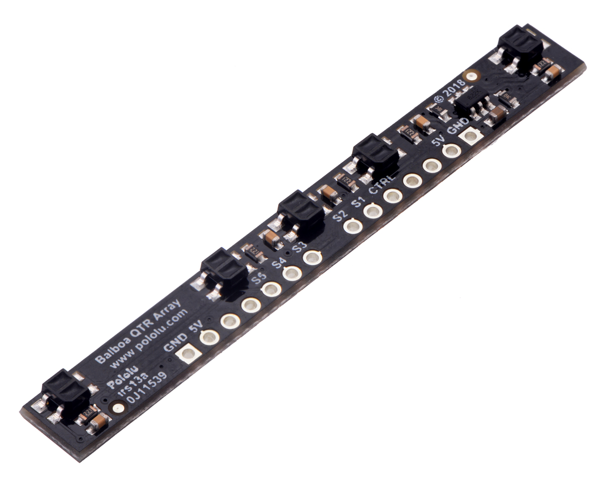

We now have a 5-Channel Reflectance Sensor Array designed specifically for use with the Balboa 32U4 Balancing Robot. The array mounts to the Balboa 32U4 control board and provides an easy way to add line sensing to the Balboa (but following a line while balancing is actually kinda hard—and that part is up to you, should you accept the challenge).
The array features five IR emitter/phototransistor pairs with dimmable brightness control similar to our line of QTR reflectance sensors.
As with all of our new products this year, we are offering an introductory special. The sensor by itself is already inexpensive, so just discounting that did not seem exciting enough. To make it more celebratory, we decided to offer a special promotion for the whole Balboa package: you can get a Balboa 32U4 robot kit with motors, wheels, and the new 5-Channel Reflectance Sensor Array for just $79! To get the discounted price, add this special promotion product bundle and coupon code BALBOAREFLECT to your cart. Offer is limited to the first 100 customers, limit one per customer. If you already have a Balboa, or if you want different motors or wheels than what’s included in the bundle, you can use coupon code BALBOAREFLECT2 to save 35% (limit 2 per item).

Related products

Closed December 25
 |
We will be closing early on Monday, December 24, so our same-day shipping cutoff will be noon Pacific time instead of the usual 2 PM. We will be closed for Christmas on Tuesday, December 25. Orders placed after noon Pacific time on Monday, December 24 will be shipped on Wednesday, December 26.
And last call for our Christmas sale — only about 12 hours to go! Merry Christmas!

New products: special servos with position feedback
|
|

We are excited to announce the newest additions to our selection of servos:
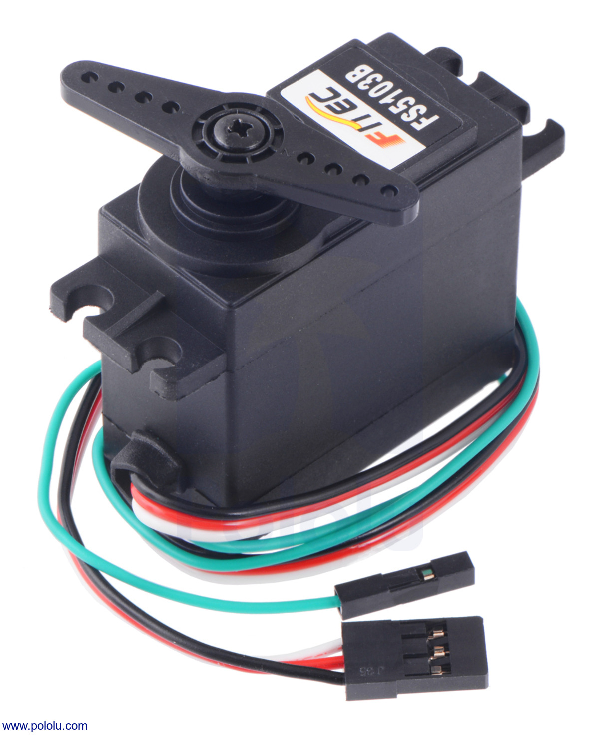
- FEETECH FS90-FB Micro Servo with Position Feedback
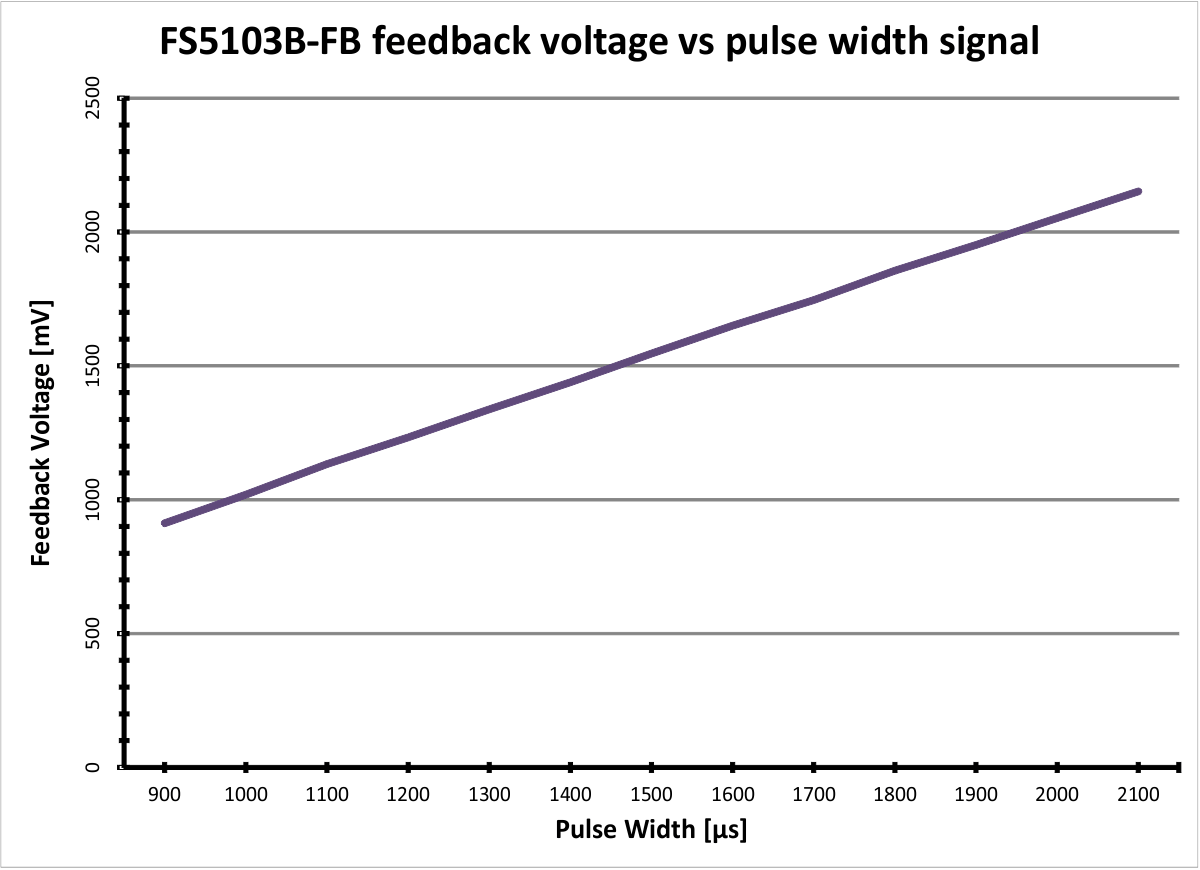
- FEETECH FS5103B-FB Standard Servo with Position Feedback
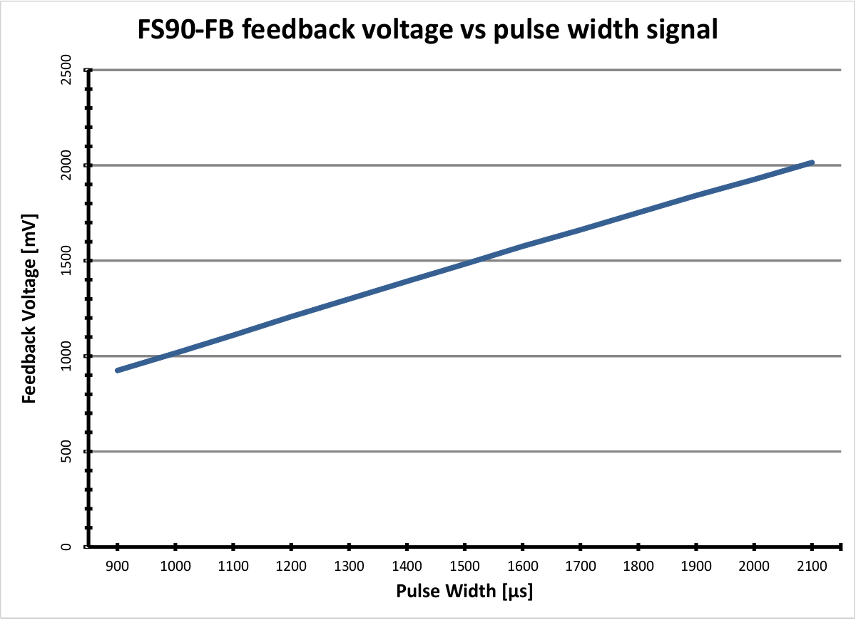
These specially modified versions of the standard FEETECH FS90 and FS5103B servos provide direct access to the feedback potentiometer through an extra fourth wire. Additionally, the FS90-FB has an extra long cable relative to the standard FS90 micro servo. The inclusion of a feedback wire allows you to monitor the servo’s position, which is especially useful for more complex robotic applications. For example, it can be used for determining if the servo is stalled or when it has reached it’s target position. It also allows you to implement your own higher-level closed-loop position control or create servo movements by hand that you can record and play back later. This feedback voltage varies linearly over the servo’s range of motion.
 |
 |
These servos are similar to those used in the Robot Arm Kit for Romi and Micro Gripper Kit and can be used as replacements for those servos.
These are just the start of our eventual selection of FEETECH servos with position feedback, so keep an eye on our blog and New Products category for more to come!
Related products


(A little more than) twelve days of Christmas sale

If you missed our Black Friday sale or realize you didn’t quite get everything you wanted, don’t fret: we have all active Pololu-brand and PCX products on sale for 12% off, and we are offering 15% off twelve broad categories of our products. The sale runs through Friday, December 21, but be careful to order early for delivery before Christmas. Save on your Christmas shopping, or stock up now on robot parts for the new year. Check out the sale page for all the discounts and coupon codes. Merry Christmas!


Home | Forum | Blog | Support | Ordering Information | Lists | Distributors | BIG Order Form | About | Contact
© 2001–2026 Pololu Corporation


