Pololu Blog »
New product: VL53L5CX Time-of-Flight 8×8-Zone Distance Sensor Carrier
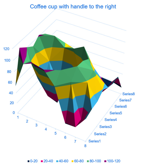
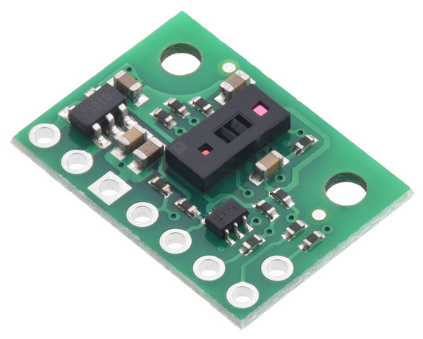
I’m excited to announce the release of our new VL53L5CX Time-of-Flight 8×8-Zone Distance Sensor Carrier! Over the past several years, STMicroelectronics has introduced a number of FlightSense distance sensors, starting with the VL6180X, that use time-of-flight (TOF) measurements of infrared laser light to measure distances. Each new sensor has been more capable than the last (usually offering an increased range), but the VL53L5CX is more than just another incremental upgrade. What makes the VL53L5CX really special is its ability to take readings of multiple targets across a grid of multiple zones, allowing you to generate a depth map with up to 8×8 resolution and 4 m range.
 |
A plot of a coffee cup as detected by a VL53L5CX time-of-flight 8×8-zone distance sensor. |
|---|
Compared to sensors that only give a 1D measurement, the VL53L5CX does demand more from a microcontroller to support its operation as a 3D lidar. Initializing the sensor through I²C and processing its data requires a lot of RAM and program memory, so it is not practical to use the VL53L5CX with most 8-bit MCUs like the Arduino Uno. (The same was true for the VL53L3CX, which shares the VL53L5CX’s multi-target capability but does not have multi-zone capability.) We found that the Raspberry Pi Pico’s RP2040 microcontroller worked well for interfacing with the VL53L5CX, and other similarly powerful 32-bit controllers like an ESP32 should also work.
 |
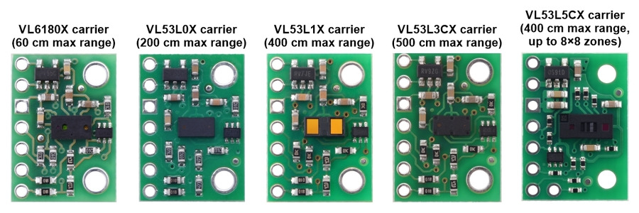
It’s fun to compare our VL53L5CX carrier with our other ST time-of-flight sensor boards because even though the boards are the same size (and pin-compatible), the VL53L5CX component itself is significantly bigger than its predecessors. We also switched from using 0603-size surface-mount resistors (0.06″ × 0.03″, or 1.5 mm × 0.8 mm) to 0402-size parts (1 mm × 0.5 mm) to help everything fit in the same form factor, and that makes for even more contrast with the large IC. As we refine our manufacturing abilities to let us work with more challenging parts like these, it’s nice to have more options for making things even more compact. (When can we try some 0201 parts?)
2 comments
I am wondering what configuration you used for the Sensor. Multizone mode with continous conversion? And what about integration time and measuring frequency? Currently i am working on a depth map with the VL53L5CX but the values i get from measuring are not precise. Did you calibrate the sensor before use? If so how did you do it?
Thank you!
I mostly used the examples included with ST's VL53L5CX ULD API as a starting point for testing the sensor. I generally used continuous mode and the maximum frequency available (60 Hz for 4x4 zones or 15 Hz for 8x8). I don't think I did much to change the default integration time or try to calibrate the sensor.
If you continue to have trouble, you might want to post on our forum or ST's community site (they are usually pretty helpful if you have specific questions about setting up the sensor or how it works).
Kevin


