Pololu Blog »
New D24V150Fx 15A step-down voltage regulator family — our highest-power regulators yet!
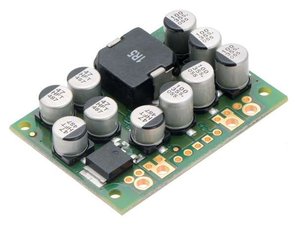
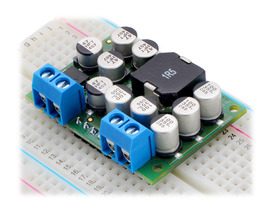
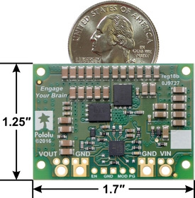
I am excited to announce that we just released our highest power regulators ever. The new D24V150Fx family of step-down regulators includes units with 3.3 V, 5 V, 6 V, 7.5 V, 9 V, and 12 V outputs and can output currents of around 15 A! With all of the output voltages available, the D24V150Fx family of regulators is great for a variety power-hungry projects like running servos or our metal gearmotors and supplying large LED displays.
|
|
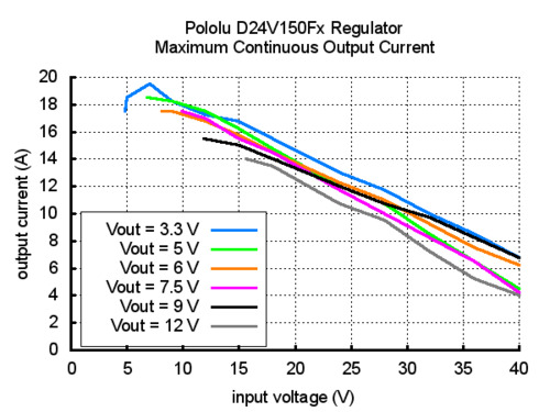
The maximum continuous output currents for all the members of the D24V150Fx family are shown in the graph below. You can see that the available output current is generally a little higher for the lower-voltage versions than it is for the higher-voltage versions, and it decreases as the input voltage increases.
 |
These regulators accept input voltages up to 40 V and have typical efficiencies between 80% and 95%. Integrated reverse-voltage protection, over-current protection, over-temperature shutoff, undervoltage lockout, and soft-start features make these regulators robust, and a power good output can be used to monitor the output voltage.
See the product pages for any of the D24V150Fx regulators for more information on these new regulators, or visit our voltage regulator category to see all of our regulator options.
20 comments
what about voltage ripple on this unit?
We do not have that characterized, and I do not have a setup to test it well, but I put a 6 V unit on my scope with 24 V in, and I'm seeing around 35 mV peak to peak across a wide range of loads.
-Claire
I would like to know what are the operating temperatures of the 5V 15A regulator, and what is the threshold before thermal shutdown occurs?
We do not have the available output current vs. ambient temperature characterized (the available current depends on several factors). In general, the regulator is limited by heat dissipation, and the higher your ambient temperature, the less current will be available. The maximum continuous current graph on the product page is for the hottest part of the board getting to 125°C; the thermal shutdown is around 160°C, inside the regulator IC.
-Claire
We have not characterized these regulators with heatsinks, but you could try adding one to see how much improvement you would get. It would probably be most effective on the silkscreen side of the board above the two large FETs. Additionally, we have generally found forced airflow to be more effective than a heatsink alone. For fun one of our engineers designed a fan enclosure for these regulators and in some brief tests was able to get several extra amps out. If you have access to a 3D printer and want to try it out, you can download it from Thingiverse. If you do try that enclosure or heatsinking, we would be interested to hear how it goes.
-Claire
It shows in all of the images that there are multiple GND's. Are all the GND's connected or is the GND next to the Vin different than the GND next to the Vout?
Thanks!
Yes, all the grounds on those boards are tied together.
-Dan
Do you have right angle headers with pins long enough for the +VOUT and GND holes?
We do not carry right-angle male header pins in that size, and I do not have a specific suggestion for a supplier.
Please note, our header pins can only handle about 3A per pin, so if you are running more than 6A for your setup, it would be better to do something like use the supplied terminal blocks or solder wires directly to the board.
-Dan
Or, is it necessary to use both ground wire connections?
The DC current through the ground connection is relatively low; however, if you do not connect both grounds, it negatively affects the AC aspect of the regulator switching and increases both electrical noise at the load and radiated emissions throughout the circuit, so we do not recommend having a single ground connection.
-Tony
cant you company make this cooling fan system fore the units and selling it as a complite kit
https://www.pololu.com/blog/628/new-d24v150fx-15a-step-down-voltage-regulator-family-our-highest-power-regulators-yet#post-comment
Things like the available space, direction of airflow, and amount of airflow you need are going to be very specific to the overall system, so I do not expect to offer a regulator like this with a particular fan as a general stock product. Can you share more about your application and what kind of a fan setup would be good for you?
- Jan
The soft-start circuit uses a capacitor to time how quickly to let the output voltage rise during startup. If you email us, I can send you a picture that shows where the soft-start capacitor is on the board.
-Claire
http://www.enzotechnology.com/mos-c1.htm
Can you give some advice, thanks.
We have not characterized these regulators with heatsinks, but you could try adding one to see how much improvement you would get. It would probably be most effective on the silkscreen side of the board above the two large FETs. We have also generally found that forced airflow is more effective than a heatsink alone and one of my previous posts has a link to a 3D printable enclosure that fits a fan. Note that for most input and output voltage combinations 8A should not be an issue without additional cooling.
-Claire
We have tested these regulators at their maximum input voltage, but to the best of my knowledge we have not observed ourselves or heard of anyone else observing behavior like what you described, so there might have been a problem with your setup or that particular regulator. The comments for this blog post are not a good setting for troubleshooting discussions, so please email us, and we would be happy to help figure out what might have gone wrong. In your email, I recommend including a reference to your comment here, your order information, and some pictures of your board and setup.
- Patrick


