Pololu Blog »
New product: VL53L0X Time-of-Flight Distance Sensor Carrier
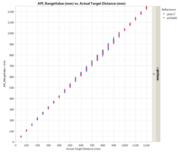
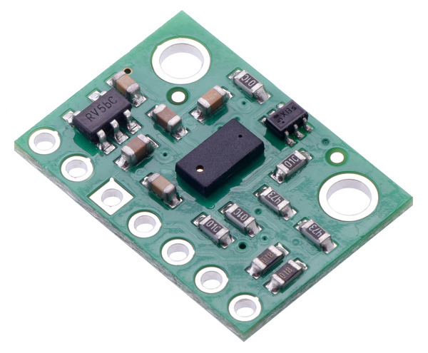
We’ve just released our VL53L0X Time-of-Flight Distance Sensor Carrier. With its ability to measure distances up to 2 m depending on configuration, target, and environment, the VL53L0X is a longer-range version of the VL6180X (but without ambient light sensing functionality) that operates using the same principles. This integrated lidar module times how long it takes for pulses of infrared light to reach a target, reflect off it, and arrive back at the sensor. It uses this information to report the range to the target with a resolution of 1 mm and accuracy as good as ±3%, minimizing the effect of the target’s reflectance on the measured distance.
 |
VL53L0X datasheet graph of typical ranging performance (in default mode). |
|---|
As usual, our breakout board adds a 2.8 V regulator and level shifters to help interface with 3.3 V and 5 V systems, as well as a breadboard-compatible pinout and mounting holes. We are also working on an Arduino library for the VL53L0X that we expect to release in the next few days.
For more information about the VL53L0X carrier, see its product page.
10 comments
Trying to figure out how many measurements can be made per minute.
Thanks!
bool setMeasurementTimingBudget(uint32_t budget_us)
Sets the measurement timing budget to the given value in microseconds. This is the time allowed for one range measurement; a longer timing budget allows for more accurate measurements. The default budget is about 33000 microseconds, or 33 ms; the minimum is 20 ms. The return value is a boolean indicating whether the requested budget was valid.
Yes, that is correct. Thank you for following up and letting us know you figured it out.
-Jon
I would like to use it in a low power application, and am using the arduino library, but for some reason the software standby takes up 80uA and when I use xshut (low to HW standby and high to use sensor) it uses 150uA in standby :S
Is this because of the board components, or am I missing anything? I tried connecting XSHUT and setting pinmode INPUT_PULLUP as suggested in the documentation, to prevent energy leak, but I did not notice a difference.
Kind Regards.
There is 48k ohms of resistance between the 2.8V VDD rail and the XSHUT pin on the header. We would expect that resistance to draw about 60uA when the XSHUT input is grounded. You can refer to the schematic diagram on our product page for more information about how that pin is connected.
If you want more help in determining the best way to put the sensor into standby, our forum is the best place to post your questions.
-Nathan
We're thinking of using several, but I'm not sure how to change the I2C address.
I see this line:
void setAddress(uint8_t new_addr)
Changes the I²C slave device address of the VL53L0X to the given value (7-bit).
I'm having some trouble making this work.
Any hints?
Thanks
Just saw the answer on the forum
You guys are Great!
Are you planning on making the VL53L1X version of the sensor?
If so, how long before you sell it to the public?
Best,
Yes, we are planning on that. We have the sensor chip on order, but with the crazy lead times lately, it might still be a few months before we get them.
- Jan


