Pololu Blog »
Sumo ring border angle detection
My robot from the last LVBots mini-sumo competition has a feature which I think is pretty interesting and sets it apart from a lot of other robots: when it detects the border of the sumo ring, it measures the angle of the border and uses that information to try to get to the center.
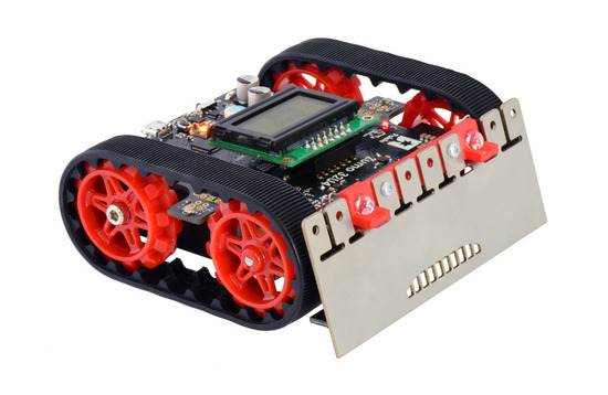
The name of my robot is Zumo Red, and it is a Zumo 32U4 Robot Kit with 75:1 HP micro metal gearmotors. Zumo Red has special red sprockets and a red LED holder, but other than that it is just a normal Zumo 32U4 with integrated encoders, line sensors, and a gyro, which were all useful for finding the center of the ring.
 |
Zumo Red, a Zumo 32U4 with red sprockets and a red LED holder. |
|---|
My idea was that the center of the ring is the farthest spot from the edge, so it is the safest spot to be in, and my robot should try to get there. You can see an example of this behavior in the video of Zumo Red vs. Sumo Neko. After pushing its opponent out of the ring, Zumo Red measured the angle of the border, drove to a spot near the center of the sumo ring, and started scanning for opponents again.
The rest of this post explains the principles I used to measure the angle of the border.
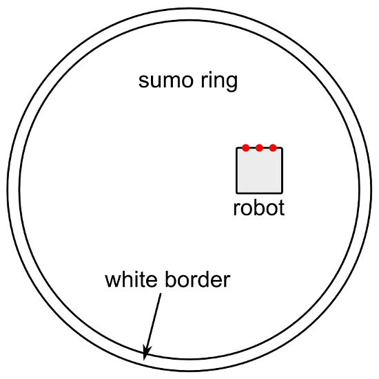
Let’s start by sketching out the basic situation. The diagram below shows the sumo ring and a robot inside it. The three red dots represent downward-facing line sensors that are used to detect the white border of the ring. The main purpose of these sensors is to allow the robot to know when it is about to drive out of the ring, allowing it to turn around and save itself. We’ll assume that the robot has an identifiable front side that is usually facing towards the direction of motion whenever the robot is driving. We’ll assume that the line sensors are near the front side, and arranged in a line that is parallel to the front side.
 |
Diagram showing a Mini Sumo ring and and robot. The red dots represent downward-facing line sensors on the front of the robot that are used to detect the border. |
|---|
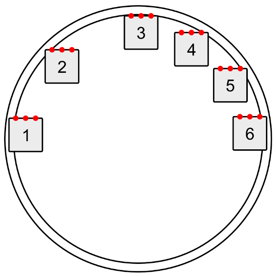
We need to get an understanding of all the different ways the robot could be oriented when it starts detecting the border with its sensors. The picture below shows some example orientations for the robot.
 |
Some possible positions a robot can be in when it senses the border of the sumo ring. |
|---|
The angle that the robot is facing does not matter, because the sumo ring has rotational symmetry. In other words, every border-detection scenario can simply be rotated until the robot is facing towards the top of the diagram without changing anything important. Therefore, we can just consider the cases where the robot is facing towards the top of the diagram and forget the other cases, which makes our job a lot easier.
We will also assume that the robot is driving straight forward. If it is driving in reverse, driving along a curve, or getting pushed by another robot, the technique presented here for measuring the angle will probably not work. Since it is driving towards the top of the diagram and starts inside the ring, there is no way for sensors to detect the lower half of the border. The robot is going to drive forward and sense some part of the upper half of the border.
If the leftmost sensor sees the border first before any of the other sensors do, the robot will know that it is in the upper-left quadrant of the diagram above, like positions 1 and 2. If the rightmost sensor sees the border first, the robot will know it is in the upper-right quadrant, like positions 4, 5, and 6. If the robot is in position 3, where both sensors detect the border at nearly the same time, the robot could decide it is in either quadrant, and that is okay. Because the interior of the sumo ring is concave, the first sensor to see the border will usually be the leftmost or rightmost sensor; it would be unusual for an inner sensor to see the border first.
Therefore, as soon as the robot sees the border with a sensor, it knows what quadrant it is in, and it can use that information to decide which direction to turn. This is what our simple BorderDetect example for the Zumo 32U4 does. It knows what quadrant it is in, but beyond that it does not know where it is.
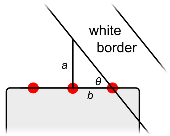
This close-up diagram shows the situation when the rightmost sensor detects the border:
 |
The right triangle that is formed when a sumo robot first senses the white border with its right-most sensor. |
|---|
A right triangle is formed with perpendicular sides a and b, as shown in the picture above. We can use trigonometry to find the angle θ (theta). By the definition of the tangent function, the tangent of θ is equal to a divided by b. Therefore, a formula we can use to calculate θ is:
``θ = arctan(a / b)``
If you are programming your robot in C or C++, you can use atan, a function from the C standard library, to compute the arctangent.
The value of a can be measured with the robot’s encoders. The robot can drive forward until the middle sensor detects the border and measure how much distance it traveled to get there.
The value of b is just the distance between the two sensors involved, so it is a constant property of the robot that should be entered into your code ahead of time. The value of b can be calculated by measuring the distance between the two sensors. However, you should make sure that the value of b in your code uses the same units as the value of a, or else you will not get the correct ratio when you divide them. Since a comes from the encoders, converting b into the same units involves knowing the number of encoder counts per motor revolution and the diameter of your robot’s tires/treads. Instead of calculating or looking up those numbers, I think the easy way to get b is to take some measurements of a and θ and pick a value for b that fits your data. That’s what I did for Zumo Red: I made it to drive forward to the border, measure a, and stop moving. Then I used its gyro to measure θ as I manually turned it towards the center. I repeated this process several times at different locations on the ring. Collecting this data and plotting it gave me confidence that my procedure for measuring the angle would actually work, and it helped me determine the value of b.
Once the robot has computed θ, it can calculate the angle it needs to turn to face towards the center, φ, with this formula:
``φ = 180° – θ``
The robot can use either a gyro or its encoders to perform a measured turn towards the center. The Zumo 32U4 has an integrated gyro, so that’s what I used in my robot. However, encoders would probably work too if your robot does not have a gyro.
If you would like to see a working code base that integrates the techniques discussed here, you can check out the code in my zumo-red repository on GitHub. That code is designed to run on a Zumo 32U4 with 75:1 HP motors, so you should be able to get the code working without writing any code of your own.
Zumo Red ended up tying for 7th place in the LVBots contest (which had 18 robots). It won against Venom, lost to Dkunrtakd, won against Sumo Neko, won against Covert Ops, and finally got knocked out of the tournament by Brandon’s Black Mamba. I didn’t add any extra weight to Zumo Red, so it weighed only 273 g, which is probably why it only succeeded in pushing robots out of the ring when it was lucky enough to get at them from the side or rear. If I had gotten the weight closer to the 500 g limit, it might have been able to push some robots out the ring head-on and get a better ranking.
If you make a robot that measures the angle of a sumo ring or does something similar, please let us know your results in the comments!


