Pololu Blog »
New product: Pololu Dual MC33926 Motor Driver for Raspberry Pi
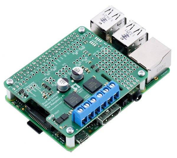
The Pololu Dual MC33926 Motor Driver for Raspberry Pi is our latest offering designed to help you build a robot around the powerful and versatile Raspberry Pi single-board computer. It features a pair of Freescale MC33926 motor drivers, each capable of supplying a motor with up to 3 A continuous (5 A peak) at voltages from 5 V to 28 V. This makes it a good choice for driving bigger things like our 25D and 37D motors and even linear actuators.
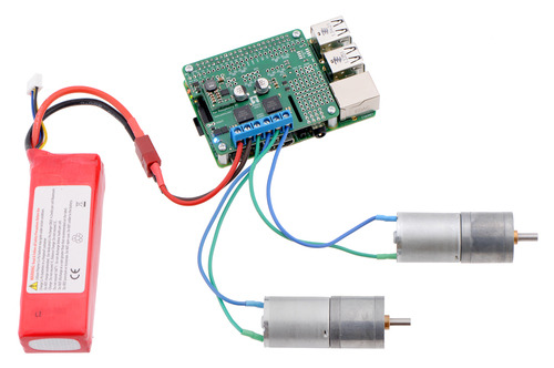 |
Driving motors with a #2756 dual motor driver on a on a Raspberry Pi Model B+ or Pi 2 Model B. A step-down regulator provides 5 V to the Raspberry Pi. |
|---|
We particularly like using the MC33926 because of its robustness: it can withstand voltage transients up to 40 V, and it has a current regulation feature that actively limits the output current to a safe amount. Furthermore, the driver automatically lowers the current limit as its temperature increases, allowing it to gracefully reduce the motor current instead of abruptly shutting down.
This add-on board is a step up from the relatively minimal, lower-power DRV8835 motor driver expansion we released last year, but it is just as easy to use. Our Python library helps you quickly get your motors running with the board’s default pin mappings, which use logic gates to enable drive/brake operation of the MC33926 drivers with only two control pins per motor.
Additional inputs and outputs on the MC33926 drivers are exposed for advanced users who want to make use of other configurations and control methods, and a small prototyping area on the side of the board provides a convenient space for adding custom circuits. As with the DRV8835 board, you can optionally connect a voltage regulator (not included) to power the Raspberry Pi from the motor power supply.
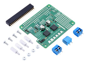
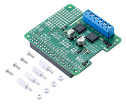
The motor driver board is available in two versions:
- a partial kit, with connectors included but not soldered in
- fully assembled, with the female header and terminal blocks soldered to the board
|
|
If you’re familiar with other Raspberry Pi add-on boards, you might find it unusual that we are not calling this board a “motor driver HAT”. In fact, it meets most of the requirements needed to qualify as a Raspberry Pi HAT (Hardware Attached on Top): it matches the HAT mechanical specification, and it even includes the recommended ideal diode circuit, allowing the optional regulator and the Raspberry Pi’s usual USB Micro-B power supply to be safely connected at the same time.
The reason the board does not qualify as a HAT is the absence of an ID EEPROM. Such a component is intended to allow the Raspberry Pi to identify a HAT board and configure itself to work with that board. We spent some time looking into how an ID EEPROM might help make this motor driver expansion better or easier to use, and we made provision for adding one in the design of the PCB, but eventually we concluded that it seems to offer no substantial value for this kind of board. (We’ve even seen some similar HATs from other manufacturers that ship with a completely blank EEPROM!)
Automatic configuration might be useful for making the Raspberry Pi automatically load a Linux device driver for an I²C or SPI add-on, but since this motor driver expansion is controlled with direct manipulation of GPIO pins, the responsible program or library can easily set up the pins itself before it begins driving and reading them. Other use cases, like enabling the Raspberry Pi to detect whether the HAT is connected and potentially distinguish between different versions of the HAT, would require much more complex support software to take advantage of while being of questionable benefit.
As a result, we’ve decided to omit the ID EEPROM from the board, even if that means it doesn’t meet the full HAT specification and shouldn’t be called a HAT. The EEPROM format specification still appears to be preliminary and subject to change, so it’s possible that future Raspberry Pi updates will make the EEPROM more useful; if so, we will likely reconsider the decision not to populate the EEPROM chip. However, if you think we’ve missed an argument for including an ID EEPROM now or have any other thoughts on its value, we’d be interested to hear your observations.
17 comments
No, we do not recommend connecting the MC33926 motor driver outputs in parallel to control a single motor, since timing differences in the two units might result in shoot-through. (However, you are correct; the VNH5019 motor drivers are designed so that their outputs can be paralleled.) If your application requires more current than a single driver can handle, you might consider using a higher powered one instead.
-Josh
Yes, you can access the Raspberry Pi's I2C pins through pins 2 and 3 (which are labeled SDA and SCL, respectively) on the Dual MC33926 Motor Driver board. For more details about the I/O connections between the add-on board and Raspberry Pi, see the "Pololu Dual MC33926 Motor Driver for Raspberry Pi schematic diagram" under the "Resources" tab on its product page
- Amanda
Unfortunately, we are not currently set up to be able to offer a custom soldering service like that, but we appreciate the feedback, and we will work on adding this kind of service in the future. So we have a better idea of how much this would be worth to you (and anyone else reading who would be interested in this kind of thing), can you tell me what you would be willing to pay and how many days processing delay would be acceptable?
- Ben
Couple of questions
1. Is it possible to stack 2 of these if a stackable header is used instead of a regular one ??
2. Is it possible to limit the output current available to a motor through this board ?? - I would like to limit the output to 500mA if possible
Thanks
It might be possible, but there are a few things that might limit the practicality of stacking two of this particular shield. If you are using the hardware included with the board, the screw terminals are a little bit too tall to fit underneath another board, so you would probably need another way of making those connections like soldering your motor and power supply leads directly to the board. Also, if you want independent control of the 4 channels, you would need to remap the connections (which we discuss in the user's guide for the board).
Depending on your application, you might be able to limit the current to 500mA using the current feedback feature of the driver, though you should be aware that the feedback is not very precise and might require calibration.
-Nathan
I'm a little new to robotics and the RasPI. Do I need to have the Step-Down Voltage Regulator D24V10F5 to operate this board on my RasPI? Worried if I didn't have it I might fry my board as im using 2 12v dc brushed motors on the board. My board itself will be powered from the wall outlet.
Thanks
The regulator is optional and allows the Raspberry Pi to be powered from your motor power supply. If you are powering the Raspberry Pi separately (e.g. through its USB power connector), you do not need the regulator.
You can find more information about adding the regulator in the "Powering the Raspberry Pi from the motor driver board" section of the Dual MC33926 Motor Driver for Raspberry Pi product page.
Brandon
I am installing the git clone https://github.com/pololu/dual-mc33926-motor-driver-rpi, setting up a new sd card for my robot.
The git clone is asking for a username, this didn't happen last time I cloned it in 2017.
Can anyone help please?
Thanks
Our forums are generally a better place to do troubleshooting like this; please post a description of your issue, including details on any changes you made to your system since 2017, on to our forum.
Amanda
Thanks
Eric
Our MC33926 driver carrier for Raspberry Pi will work with input voltages between 5V and 28V. Whatever voltage is applied to VIN will be the voltage out of the motor outputs, except PWM modulated. (So for a 12V supply and a 50% duty cycle, you would get results similar to running at about 6V). You will never get a higher output voltage than you input voltage.
-Derrill
Is it possible to drive a bipolar stepper motor with this board? What library should I use for it? Thanks!
I am glad you found the example Jeremy posted for how to drive a stepper motor using the MC33926 Motor Driver Shield for Arduino. However, please note that a few posts later, he posted an improved version that fixes a mistake and adds the ability to limit the maximum coil voltage to prevent damage to your motor if you are using a stepper motor with a rated voltage lower than the MC33926 shield's.
Additionally, while it is possible to drive a stepper motor with this shield, we generally recommend one of our many dedicated stepper motor drivers. or controllers instead. They offer more advanced features like current limiting, multiple step resolutions (some down to 1/256), and come in a much more compact size. Some of the drivers have higher level interface options like SPI, and our Tic stepper motor controllers offer many interface options including USB, TTL serial, I2C, hobby RC, analog voltage, and quadrature encoder input as well as the more standard STEP/DIR inputs. They also have settings that can be configured to control the speed profile, limit switches, a homing procedure, and much more.
Brandon
