Pololu Blog »
Jamee's dead reckoning robot
 |
Several Pololu employees made robots for the LVBots dead reckoning competition. Unfortunately, my robot didn’t work enough in time for the competition, but perhaps the description of my robot might give you ideas for your own dead reckoning robot.
Mechanical design
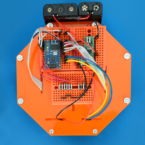
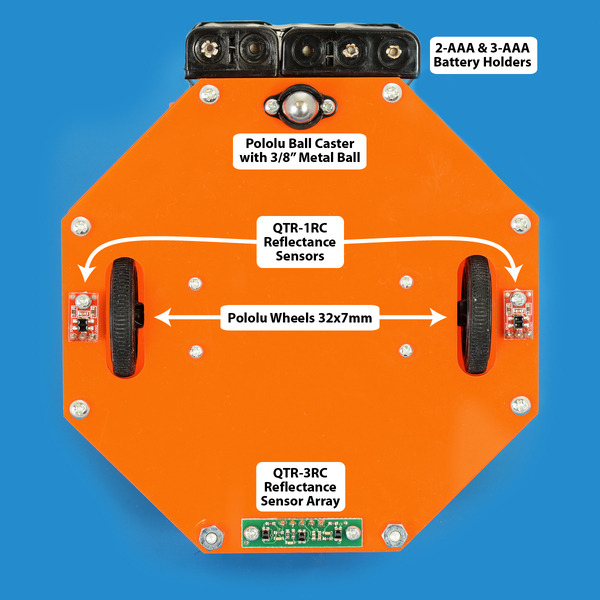
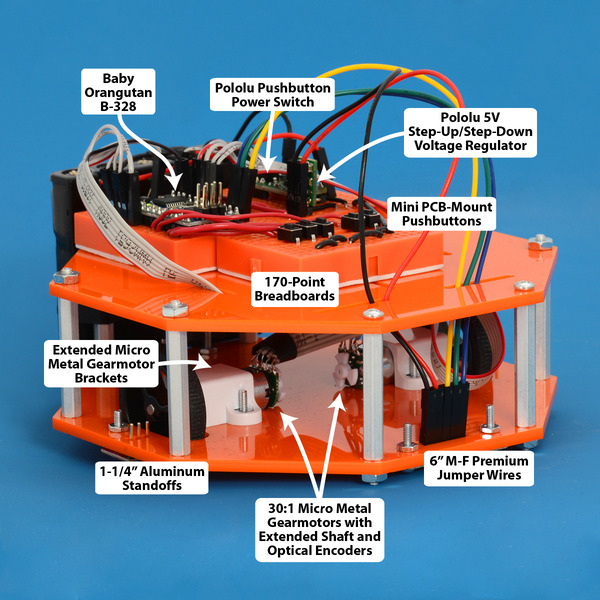
Brandon thought it would be fun if I based my robot off of his and changed it to be an octagon instead of a hexagon. The laser-cut chassis is made up of two pieces: the bottom piece holds the motors, ball caster, and QTR sensors, while the top piece carries the microcontroller, regulator, pushbutton power switch, breadboards and buttons. I attached the battery holders in the back for convenience. I chose our 1-1/4 in. aluminum standoffs to maximize the space between the two chassis pieces just in case I needed more room for components. Brandon modeled my robot in SolidWorks and I asked him to add slits in the top piece so that the wires could be placed neatly. Since our robots were similar, I chose the 3/8 in. ball caster which would extend below the chassis a little more than the wheels (shown in the picture below) and cause the robot to tilt forward slightly. This ended up being advantageous as it moved the reflectance sensors closer to the ground and closer to their optimal sensing distance of 3 mm.
 |
 |
Complete parts list
Mechanical parts:
- A custom chassis laser-cut from 1/8" acrylic
- Pololu 32×7mm wheels
- 2 × 30:1 Micro Metal Gearmotor HP with Extended Motor Shaft
- 3/8 in. metal ball caster
- Pololu micro metal gearmotor brackets
- Aluminum standoffs, various screws, nuts, and electrical tape
Power:
- AAA NiMH batteries
- 2-AAA battery holder
- 3-AAA battery holder
- Pololu Pushbutton Power Switch SV
- Mini PCB-Mount Pushbuttons (used for testing)
Sensors:
- Optical Encoder Pair Kit for Micro Metal Gearmotors, 5V
- QTR-3RC Reflectance Sensor Array
- QTR-1RC Reflectance Sensors (attached, but not used for this competition)
Electronics:
- Baby Orangutan robot controller
- 3 170-point breadboards
- Pololu 5V Step-Up/Step-Down Voltage Regulator S7V7F5
- Various wires and headers
Electronics and code
I named my robot O2 because it is both orange and octagonal in shape. I chose to use the Baby Orangutan robot controller because I had experience using it from a previous robot competition, it is small, and it has integrated motor drivers. I used our optical encoders with our 30:1 micro metal gearmotors with extended shafts. I used our 32×7 mm wheel because I figured their narrow width would help prevent slipping that can occur with wider tires. I also wanted O2 to transition to a maze-solving robot after this competition, so I used our QTR-3RC reflectance sensor array as a main line following sensor and two QTR-1RC reflectance sensors as optional supporting sensors on each side. To power my system, I used 5 AAA batteries, housed by a 2-AAA Battery Holder and 3-AAA Battery Holder, combined with an 5V Step-Up/Step-Down Voltage Regulator S7V7F5 to control the voltage to the QTR sensors and encoders.
My original strategy for the competition was to have my robot successfully line follow the course and when it got to the end, it would randomly turn in a direction and move forward for a time. On the day of the competition, I was encouraged to try to use the encoders to properly dead reckon, so I scrapped my code and used Paul’s code as a starting point (the same Paul who ultimately won the dead reckoning competition). The encoders were giving me unexpected readings, so I resoldered the wires. The signal from one of my encoders was still too low to ever read high, so I boosted the signal by enabling the internal pull up on the appropriate pins. This worked nicely. I continued trying to test and figure out how to use the encoders, but when I saw there was only a couple of hours until the competition, I reverted back to my original unfinished code. I tried to at least get my original strategy working, but ran out of time. I plan to get this robot working for the next competition, maze solving.


