Pololu Blog »
PID line follower with 5" robot chassis
Posted by Claire on 18 April 2014
4 comments
Tags: community projects
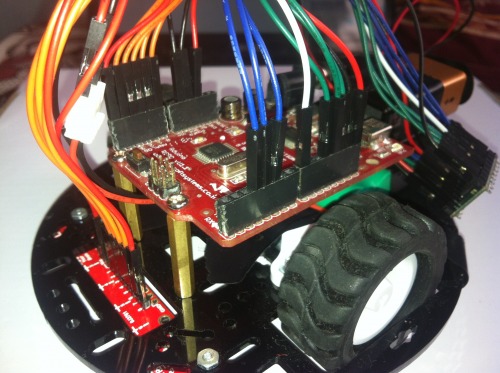
This PID line follower, originally featured in this Let’s Make Robots post by user Enigmerald, uses our 5" Robot Chassis along with 30:1 MP micro metal gearmotors, extended brackets, and our 42×19 mm wheels. Our QTR-8RC Reflectance Sensor Array is used to sense the line and our TB6612FNG carrier, along with an Arduino-compatible controller, is used to control the motors. A diagram of how everything is connected and the code for the robot are available in Enigmerald’s post. The post also has a link to a basic tutorial on PID tuning using the QTR array.
 |
4 comments
Hello,
I would like to know how did you implement PID Algorithm? If possible send the arduino code you use
I would like to know how did you implement PID Algorithm? If possible send the arduino code you use
Hello, vinay.
The maker of that robot, Enigmerald, links to a tutorial about PID for line following that they wrote.
-Jon
The maker of that robot, Enigmerald, links to a tutorial about PID for line following that they wrote.
-Jon
Hi,
I see from the Pololu TB6612FNG dual motor driver's description that Vcc is not protected against reverse polarity. I checked to see if anything on this was covered in the tutorial and it was not.
Could you tell me how to best protect Vcc against reverse polarity please?
Thanks
Matty
I see from the Pololu TB6612FNG dual motor driver's description that Vcc is not protected against reverse polarity. I checked to see if anything on this was covered in the tutorial and it was not.
Could you tell me how to best protect Vcc against reverse polarity please?
Thanks
Matty
Hello, Matty.
You could add your own reverse voltage protection circuit to the Vcc pin. By the way, just to be clear, reverse voltage protection is to prevent damage in the situation where the Vcc connection is accidentally made with the wrong polarity (e.g. connecting ground to Vcc and your logic voltage to ground). So, if you put together your system in a way that the Vcc connection is made through a keyed connector, that might also be a solution.
If you have additional questions or concerns, please post on our forum, which is more suited for technical discussions, and we would be glad to continue the discussion there.
Brandon


