Pololu Blog » Engage Your Brain »
Force and torque
I got a few private requests for more information about torque after my post on units, and since torque is relevant to the next few posts I want to make about servos, I’ll try to explain torque a bit more today. Torque is intimately connected to force, so we’ll start with a review of Newton’s first two laws of motion. You should know some basic calculus to really understand these concepts, but getting into that is beyond the scope of this post; I hope I hit the right level of simplification to provide some useful knowledge to those who have some basic intuitive mechanical sense but have not taken, or have forgotten, basic physics courses. There are many more complete explanations available all over the internet; my goal is to offer a summary of some basics you should know and how they might apply to simple robotics problems.
Force and acceleration
Forces change the way things move. Without any force acting on it, an object that is moving will continue moving at the same speed and in the same direction, and an object that is not moving will remain at rest. If there is a force on an object, that object will accelerate: a stationary object will start moving, and a moving object might speed up, slow down (deceleration is just acceleration in the other direction), or change direction. Forces have directions and add up; if you have forces in opposite directions, they can cancel each other out. If you’re getting dragged along by two dogs on leashes, and one wants to go forward and left and one wants to go forward and right, the left and right components might cancel out, but their forward components will still add up and accelerate you down the sidewalk. If you have a small dog and a big dog that want to go in opposite directions, you’ll end up going in the direction the big dog is pulling, just not as quickly as if the small dog were not helping you slow down.
All the objects around us actually have many forces acting on them all the time; the only reason everything isn’t flying around is that the forces balance out. When you drop a pen on a table, gravity keeps pulling it down, but the table pushes up with enough force to counteract gravity and keep the pen stationary. So, practically speaking, we are concerned with net forces, and my “if there is a force on an object…” statement above was really about a net force since everything has some forces on it despite not accelerating.
Calculating the exact details of how things move is where the complicated calculus comes in. However, you should at least know the basic equation that is at the heart of Newton’s second law of motion: F = m a. (The ‘F’ and ‘a’ are bold because they are vectors, meaning they have directions, but for simple calculations, you can keep things in one dimension and think of it as F = ma.) This means that for a given force, an object will accelerate twice as much as an object with double the mass, and if you double the force, you double the acceleration. Acceleration is the rate at which speed is changing, so as long as you keep applying a net force to an object, it will keep changing speed at that rate; in other words, the object will keep moving faster and faster. The reason things do not keep accelerating is that all kinds of opposing forces get bigger with speed. That’s why there is a terminal velocity for skydivers: gravity alone would keep making the free fall speed faster, but air resistance eventually gets large enough that it balances out gravity. Similarly, a motor won’t forever make your robot run faster because eventually, various frictions and other resistances will get large enough that all of the effort of the motor will go into overcoming them rather than into more acceleration.
Units of force and acceleration
The basic concept relating force and acceleration should be fairly familiar or at least easy to follow (though it took humans centuries to figure it out), but things get less familiar when we talk about the units. Terms like “acceleration” or mentions of the pounds of thrust from a jet engine are more common than standard units for acceleration and force, m/s2 and newtons. Dividing by square seconds might be a difficult concept to accept, and so it might be easier to think of acceleration as speed per time, such as meters per second per second.
 |
Let’s consider the familiar example of car acceleration. If a car can go from “0 to 60” in ten seconds, that means that in ten seconds, it can accelerate from standing still to a speed of 60 miles per hour, which is about 90 feet per second. That is a change of speed of 90 feet per second in ten seconds, or averaged over those ten seconds, nine feet per second per second—after every second, the car is moving 9 feet per second faster than the previous second. Since things like air resistance get worse at higher speeds, the actual acceleration likely drops with every passing second, but the point is to illustrate how we get to units like distance per second per second or distance per second squared.
The most standard unit for force is the newton, abbreviated N, which is the force to accelerate one kilogram at one meter per second squared. That is, 1 N = 1 kg⋅m/s2. We should note that the kilogram is a unit of mass, not force; however, weight is a force. You might say that you “weigh” 70 kilograms, but that is actually your mass; the force you exert on whatever surface you are on is that 70 kg times the acceleration of gravity, about 9.8 m/s2, which comes out to about 686 newtons. If you stood on the moon, your mass would still be 70 kilograms, but your weight would be about six times lower. What complicates things even more, at least for Americans, is that our standard unit of force is the pound, and we are often asked to convert pounds to kilograms without regard for the planet on which the conversion is to take place.
A source of confusion more significant than the informal conflation of weight and mass is the use of mass in technical specifications calling for force. If you see that some actuator is supposed to provide so many grams or kilograms of force, the unit is actually gram-force or kilogram-force, the weight of a gram or kilogram due to Earth’s gravity. The intended meaning is pretty easy to understand: an actuator that can provide 8 kilograms “of force” can hold up 8 kilograms (on Earth). The force is actually almost 80 N, and could hold up 48 kg on the moon, but most of us don’t have the opportunity to use our actuators there, so we don’t have to worry about it.
People have long been mixing weight and mass, and the units for them, like kilograms and pounds and ounces and grams and stones and slugs, and that is not likely to change. Unfortunately, using the unambiguous unit of newtons is least likely to be useful in everyday conversations. You could put in Fs everywhere, to help people understand you mean pound-force or gram-force, not pound-mass or gram as in mass, but most people’s reactions to a torque specified in oz(f)-in. will just be, “what the F?”. My preference is to treat the gram as a unit of mass and the pound as a unit of force, but I do not care too much in everyday English, just as “flammable” and “inflammable” meaning the same thing doesn’t keep me up at night. Fortunately, it’s usually pretty easy to figure out what people mean (and you deserve to get smacked if someone tells you their weight, and you say, “wait, on Earth?”).
Torque
Torque is kind of like the rotational, twisty version of force: if we apply a net torque to something, it will have an angular acceleration, which means that its angular velocity will change. More colloquially, applying a torque to something will make it spin. However, if we’re just playing around with small robots, we usually do not care much about angular acceleration; we care more about how much a motor can lift or how fast it can make our robot go. If we have a robot elbow or robot leg or other mechanism that cannot make a full revolution, the term “spin” might not even be on our minds. Rather, we often have actuators, such as simple motors, that happen to give us a torque as output, but we want to get back from that to a force.
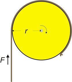
Torque is a product of force and distance, which is why we had to cover force first. Torque is often represented with the symbol τ, the lower case Greek letter “tau”. If we have a rigid rod of lenth r connected to an axle or pivot point on one end and apply a force F perpendicularly to the rod, we will get a torque of τ = F⋅r.
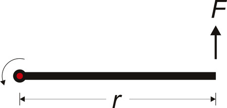 |
The rod is acting as a lever for us: if we double the distance or double the force, we get double the torque. The connection between force and torque works in both directions: you can apply a force to the rod to create a torque on the axle, or if you have an axle delivering torque, you can get a force by attaching the rod to the axle. In the second case, the longer the rod, the less force you would get at the end of it. In my drawing above, the direction of the torque is not in the plane of the monitor, so I do not have it labeled in this diagram; the curved arrow is just there to suggest the direction of rotation. Wikipedia has this nice animation showing the three-dimensional nature of torque and the angular acceleration:
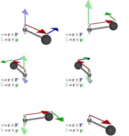 |
The blue arrow that occasionally appears is our force, which causes the rod to accelerate. The acceleration is not specifically labeled; rather, we see it in the speed of the sphere at the end of the rod and in the changing magnitude of the darker green arrow. The direction of the torque (the light purple arrow that shows up when the blue force arrow shows up) is along the axle, showing us the axis of rotation (I think further discussion of why it’s in one direction along the axis instead of the other gets us into a philosophical math discussion not unlike discussions of which way current flows). In the kinds of applications I usually see, there aren’t too many sources of torque on the same axle, and even if there are a few, it’s easy to tell if they are in the same direction and adding up or if they are in opposite directions and canceling out.
Units of Torque
Since torque is force times distance, we can use any unit we like for force and multiply it by any unit we like for distance; there is no standard unit that is not a product of the two. Unfortunately, the explicit inclusion of force carries over all of the weight/mass mess I already discussed. The newton-meter, N⋅m, is simple and unambiguous, but as with the newton, it is not commonly used, at least with the small motors and servos we tend to use in small robots. I mentioned that it’s not worthwhile to get too riled up about people using weight and mass interchangeably; however, I think it is very important to honor the multiplication of force and distance. I’ll repeat notes from my understanding battery capacity and units posts:
Torque is expressed as a force multiplied by (i.e. “times”) a distance, so “oz. in.” is pronounced “ounce-inch”, not “ounce per inch” (writing “oz/in” or otherwise introducing any notion of division is just as wrong), and an inch-ounce is the same as an ounce-inch. The hyphenation imposed by English grammar does not help matters since the hyphen looks like a minus sign when we are actually multiplying the units together.
I joked earlier about putting in Fs to clarify force as opposed to mass, but they do show up sometimes; so, in addition to kg-cm and pound-feet, you’ll also see gf-cm and lbf-ft.
Example 1: gearmotor with wheel
One of the most common torque calculations for small robots has to do with drive motors and wheels. There are two directions from which you might want to approach such a problem: starting with a known torque and then getting some sense of performance from it, and starting with a performance requirement and then calculating minimum torques required to achieve it. The second case is obviously applicable if you have many options for your motors; the first case might be more relevant if you are constrained to a particular motor because those are the rules for some contest or because that’s the motor you pulled out of your broken printer. We will go with that scenario because it’s easier for me to be specific, but you can basically reverse the order of the steps if you want to calculate minimum motor requirements. In this case, we’ll consider the maximum pushing force we can expect from a little sumo robot:
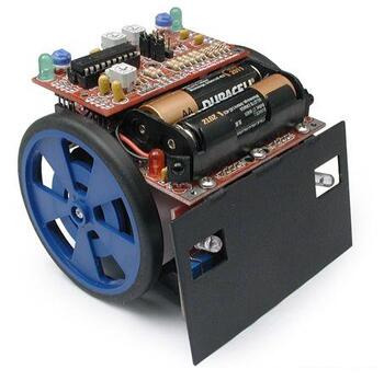 |
The robot uses Solarbotics’s 2-5/8" wheels and their GM8 gearmotor, which is a fairly typical toy motor with plastic gearbox that has a stall torque of 76 oz.in. at 6 V. (The motors are actually driven from a 9 V battery pack, but by the time the motors are stalled, the actual voltage might be around 6 V because of losses in the motor driver and drops in the battery voltage.) Here is a simple diagram of our setup:
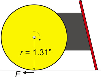 |
To get from torque to the force at the edge of the wheel, all we need to do is to correctly calculate the distance from the axle to the edge of the wheel. The 2.625" dimension is a diameter, so we need to halve that to get our effective distance. We divide the 76 oz.in. torque by the 1.31 inch distance and get a force of 58 oz., or about 3.6 pounds. We must not forget that there are two wheels, so we end up with a pushing limit of just over seven pounds. Keep in mind that this is just the limit to how much force our given motors and wheels can give us; whether the whole robot ends up capable of pushing that hard depends on many other things, such as the friction between the wheels and the ground.
If the wheel were instead a spool for winding up a string, friction would not be in play, and we would be able to transfer the full 3.6 pounds of force from the spool to the string. In this kind of application, keep in mind that we are basing these calculations on the stall torque of the motor, so with a 3.6-pound load, our winch would actually just be able to keep the spool from unwinding. It’s also not good for the motor to stall it at full power, so a more practical limit for the load might be one pound (using 30% of the stall torque).
 |
Example 2: robot arm with hobby servo
The other common example I see is a motor lifting an arm or similar mechanism through a limited range of motion.
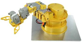 |
The calculations are basically the same for every joint; here, we’ll consider the joint that is one joint removed from the end of the arm, the joint that is red in the following diagram. Just as it’s more difficult for you to lift a weight away from your body than it is to lift it close to your body, the lifting ability for our joint in question will be worse when the rest of the arm is extended. To determine the worst-case lifting capacity, we need to determine the longest distance from the joint to the end of the arm.
 |
Let’s suppose that the maximum distance is 25 cm and that the servo we want to use for the joint has a maximum torque of 10 kg-cm. Dividing the torque by the distance suggests that the arm could lift 400 grams in that configuration. However, that simple result does not take into account the weight of the arm and the torque needed just to hold itself up.
To factor in the torque that the robot arm imposes on our joint, you need to add up the torque from each piece of the arm. Fortunately, you don’t have to weigh and measure the location of each molecule; instead, you can weigh the whole assembly and find the point at which you could balance it, the center of mass. We can then conceptually simplify your arm to a weightless rod with a mass corresponding to the whole arm’s weight at the distance from the joint to the center of mass.
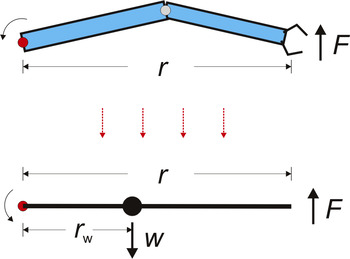 |
Let’s suppose that the arm in our example weighs 300 grams, and that the center of mass, in the outstretched configuration, is 10 cm from our joint. The arm would then put 3 kg-cm of torque on our servo, leaving us with a net maximum torque of 7 kg-cm. We then divide that by our 25 cm distance to the end of the arm to arrive at a final answer of 280 grams for the maximum that the arm could lift (assuming that the other joint is not constraining us to less than that.)
If we were unhappy about losing 30% of our lifting capacity because of the weight of the arm, we might consider adding a counterweight on the other side of the joint. This would make our distance to the center of mass (rw in the diagram) smaller and in turn reduce the torque on the joint. However, the added weight of the counterweight will add to the overall weight that the next joint in the arm (not pictured in the diagrams) has to lift, so that approach might make sense only for the first joint or only to a limited extent on the intermediate joints.
Power is not force or torque
 |
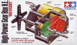 |
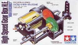
One final point for a review of force and torque is a reminder that force and torque are not the same thing as power. Power, force, and torque are specific and separate concepts, and in the context of actuators, high power is not the opposite of high speed. Power is force multiplied by speed or torque multiplied by rotational speed, so a high-torque, slow motor can have the same power as a low-torque, fast motor. The common misperception that high-torque means high-power is demonstrated in Tamiya’s high speed and high power gearbox kits. These products use the same motor, and thus ultimately produce the same mechanical power (with some small variation possible due to friction differences); however, one has a higher gear ratio than the other and trades speed for torque. In general, for a given actuator (which means for a given power), you can trade off speed for torque; however, if you want to maintain one and increase the other, you are asking for more power, and you might need to change motors.
13 comments
Now a question or two based on the string/pulley example. If I understand this correctly, and using your statement: "stall torque of the motor, so with a 3.6-pound load, our winch would actually just be able to keep the spool from unwinding" appears to be the force in kg-cm specified for the motor and this would be at stall. The other spec for the motor is the motor speed (at a given voltage) which appears to be the speed of the motor with a torque of zero or the no load speed. Is there a way of predicting the speed of the motor/gearbox as a function of the load lifted? Are there speed vs load curves? Or a rule of thumb/approximation which would assist one in selecting the motor for a given task?
Here is an example of what I want the motor to do. The motor will have a 2 cm dia pulley with a string attached to a load. I want to lift a load of 1/2 kg at 6 cm/sec (apx 60rpm motor speed). So the torque required will be 0.5kg-cm. How would I select the motor? Would the 298:1 Micro Metal Gearmotor HP do the job? I assume the motor speed running under load will be less than the spcified 100 rpm no load speed. The torque required will be less than 10% of the rated torque of the motor.
Thank you,
John Acord
- Jan
now i would like to know one additional concept along with the force at the edge of the wheel of a given radius and motor torque
according to you
"To get from torque to the force at the edge of the wheel, all we need to do is to correctly calculate the distance from the axle to the edge of the wheel. The 2.625" dimension is a diameter, so we need to halve that to get our effective distance. We divide the 76 oz.in. torque by the 1.31 inch distance and get a force of 58 oz., or about 3.6 pounds".
can i also caluclate the rpm exhibited by the motor at the above torque of the motor and wheel radius if i know the rpm rated for a motor at some voltage say 6v maybe you can tell me by considering your own example
that would help a lot to understand the charcterstics exhibited by a motor at a certain voltage and for certain weight it has to move.
at a constant voltage say 6v.
or how rpm changes for different weights the robot has to carry at the same 6v voltage.
- Jan
i will be using a 6V motor to carry no more than 1kg of mass. can you please help me go about calculating the torque i need, the diameter of the pulley and any other specifications i will need to buy the motor.
thank you
The purpose of this post is to teach you how to do these calculations yourself. I suggest carefully reading the post to see how it might apply to your project.
-Derrill
I understand Torque = Force * radius of pulley, would the force in my case be 2kg * 9.81 ? or 0.5 * 2kg * 9.81 as i have been told?
Also, this torque calculated.. would it be the same as holding torque of a motor?
Thank you
The 9.81 in your calculations indicates you are getting thrown off by thinking about the force being in Newtons, but I think you are better off thinking of your 2kg as a force since stepper motor torques are commonly specified in kg-cm, anyway. So, if you have a 2.5cm radius pulley wheel directly on your motor and hang 2kg on it, you would need 5 kg-cm to hold it. Keep in mind that the holding torque that is usually specified is a stepper motor's strongest torque, so you will need a motor with a much higher holding torque if you want to be able to lift the 2kg instead of just hold it in place.
The 0.5 factor you have in one of your alternatives makes me nervous that you are talking about some complicated system of pulleys instead of just the single wheel on the motor shaft (what I called a spool in the article). If that is your situation, you would have to say what that pulley arrangement is for anyone to be able to calculate the forces and torques involved.
- Jan
I just want to add that if your stepper motor torque is specified in N*m rather than kg*cm, then you would multiply the 2 kg by 9.81 (and don't forget to convert the radius of the pulley to meters):
torque = (2 kg)*(9.81 N/kg)*(0.025 m) = 0.5 N*m.
- Ben
I'm looking at 12v dc brushless motors... Thank you.
How much torque your motor needs is going to depend on how fast you want your three pound load to travel that one foot and various details of your specific setup (e.g. the inertia of your conveyor belt pulleys, how much friction there is in your system, etc.). This blog post might help you characterize your system and what you need more precisely, but I would additionally recommend doing some research to find what parts other people have used in similar projects.
- Patrick


