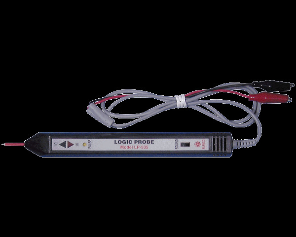
Elenco LP-535K Logic Probe Kit
This digital logic probe in kit form provides convenient and precise measurement of logic circuit signals. It displays logic levels (high or low), pulses and voltage transients down to 10 nanoseconds and a maximum input of 50 MHz. It has a large PC board and detailed manual for fast construction. The LP-535K Logic Probe kit will teach you how to solder and leave you with a very useful tool.
| Description | Specs (0) | Pictures (1) | Resources (1) | FAQs (0) | On the blog (0) | Distributors (0) |
|---|
Introduction
Assembly of your LP-535 Logic Probe Kit will prove to be an exciting project and give you much satisfaction and personal achievement. If you have experience in soldering and wiring techniques, then you should have no problem with the assembly of this kit. Care must be given to identifying the proper components and in good soldering habits. Above all, take your time and follow the included, easy, step-by-step instructions. If you are just learning how to solder, the instruction manual will walk you through proper soldering techniques.
Circuit Description
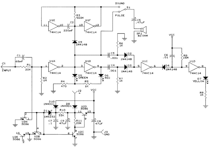
The Elenco Model LP-535K Logic Probe Kit is a convenient and precise instrument for use in the measurement of logic circuits. It displays logic levels (high or low), sounds high level, and voltage transients down to 10 nanoseconds. To detect the high and low logic levels, the LP-535 uses two inverters, U1A and U1B (see the Schematic Diagram below). One inverter drives the LO (green) LED and the other, the HI (red) LED.
The red LED lights when the input voltage is more than 50% of the supply voltage. The function of the switch for TTL or CMOS levels input signal makes up the special circuit on the base of transistors from U2 and additional components. The outputs of U1A and U1B are connected to differential circuits C3/R3 and C4/R7. These differential circuits select signals, when the test signals are the pulses. After the differential circuits, the short pulses go through inverters U1C and U1D to the yellow LED. This LED blinks when the detecting diode D4 opens. At this time, capacitor C6 discharges. The lit time of the yellow LED depends upon the value of C6. The LP-535 is equipped with a sound circuit. When the input signal is HI, the oscillator (U1E, U1F) is started and the frequency through switch S1 passes to the speaker.
- Working Voltage: 4 – 16 VDC
- Current Consumption: Max 5 mA at 5 V, Max 15mA at 15V
- Frequency Response: Over 50 MHz
- Minimum Detectable Pulse Width: 10 nsec
- Input Impedance: 1 MOhm
- Input Overload Protection: 70 V AC/DC (10 s)
- Supply Voltage Protection: 50 V AC/DC (10 s)
- Switch: Selectable Audio Indicator HI Level
 |
Elenco LP-535K Logic Probe Kit schematic diagram. |
|---|


