Electronics » Computer Interface »
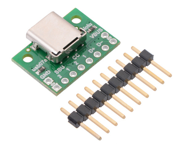
USB 2.0 Type-C Connector Breakout Board (usb07a)
This simple board breaks out the power, USB 2.0 data, configuration, and sideband pins of a USB Type-C connector to a 0.1″ spacing that is compatible with standard perfboards, solderless breadboards, and 0.1″ connectors. On-board CC pull-down resistors make it easy to use the receptacle in a power-sinking application.
 Compare all products in Computer Interface or
  Electronics Prototyping.
| Description | Specs (4) | Pictures (5) | Resources (5) | FAQs (0) | On the blog (2) | Distributors (46) |
|---|
File downloads
-
Schematic diagram of the USB 2.0 Type-C Connector Breakout Board (usb07a) (85k pdf)
-
Dimension diagram of the USB 2.0 Type-C Connector Breakout Board (usb07a) (237k pdf)
-
3D model of the USB 2.0 Type-C Connector Breakout Board (usb07a) (4MB step)
-
Drill guide for the USB 2.0 Type-C Connector Breakout Board (usb07a) (32k dxf)
This DXF drawing shows the locations of all of the board’s holes.
Recommended links
-
USB Type-C Specification
The USB Type-C Cable and Connector Specification explains technical details of the USB-C interface, including the configuration process for determining a port’s role.


