Logomatic v2 Serial SD Datalogger
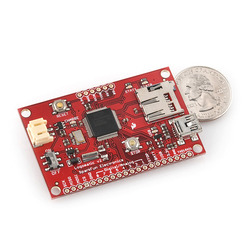
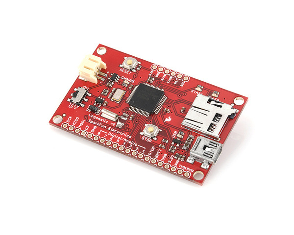
SparkFun’s Logomatic v2 incorporates an NXP LPC2148 ARM7 microcontroller with USB, LiPo battery charging, and microSD support to create a highly flexible logger. The default firmware supports serial logging and 8 channels of analog voltage logging, and a bootloader allows for custom modification of the open-source firmware without the need for an external programmer.
| Description | Specs (0) | Pictures (3) | Resources (7) | FAQs (0) | On the blog (0) | Distributors (0) |
|---|
As of March 1st, 2011, the Logomatic now ships with the MCP73831 battery charger IC instead of the hard-to-find MAX1555.
 |
Overview
The highly popular Logomatic v2 from SparkFun uses a USB mass storage stack to appear under any operating system as a flash drive. Logs are created in FAT16 format on the micro-SD media (not included) and can be downloaded quickly over a USB connection by dragging and dropping the text files from the device. The micro-SD card can also be removed and inserted into a card reader to download the logs. This board connects to a computer with a USB A to mini-B cable (not included).
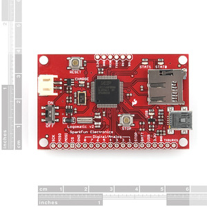
The board operates at 3.3V but has 5V-tolerant inputs, and it has a recommended supply voltage of 3.6 to 7.5 V (9 V absolute maximum). If you choose to power the board with LiPo batteries, the Logomatic v2 can charge them off of USB with its built-in LiPo charger. The power connector on the board is a 2-pin male JST connector that works with our 2-pin female JST cables. Note that the power connector is not compatible with the female connectors on our NiMH battery packs. The board’s pins have a 0.1" pitch and work with 0.1" male headers and 0.1" female headers.
The Logomatic v2 ships with basic serial text and analog logging. This firmware supports many applications, but users are encouraged to modify the firmware for their specific requirements. This firmware is open-source and available under the resources tab. The board uses an NXP LPC2148 ARM7 microcontroller that contains a USB bootloader, so it can be reprogrammed without the need for an external programmer.
Features
- Modes of operation: auto-UART, character-triggered UART, ADC
- 8 ADC channels, all selectable as on or off
- Bootloader-programmable LPC2148 ARM7 with 512K user flash
- 10 available GPIO pins
- Built-in RTC
- 2 Status LEDs
- USB Link LED
- External interrupt micro-SD socket
- Compatible with low-cost flash media up to 2GB
- Built-in MCP73831 USB charger (300mA max)
- Built-in USB mass storage device bootloader
- Integrated power switch and user-interface pusbuttons
- Recommended supply voltage: 3.6 to 7.5 V (9 V absolute maximum)
- Logic voltage: 3.3 V (from on-board 3.3V LDO regulator) with 5V-tolerant inputs
- Current draw: < 80 mA (depends on the UART logging frequency)
- Dimensions: 1.5 × 2.4"
|
|
Example Applications
- Log your travel path with a GPS module.
- Log the forces you experience on an amusement park ride using an inertial measurement unit.
- Log weather data (e.g. temperature, pressure, humidity) with a USB weather board.
- Log activity in a room with a motion sensor or a distance sensor mounted in a doorway.
- Log your robot’s battery voltage to obtain a discharge curve.
- Log your robot’s sensors or other data from your robot controller as it runs.
Note: Even though this board has 5V-tolerant inputs, it cannot measure voltages above 3.3 V. These voltages will be logged as 3.3 V.
People often buy this product together with:
 |
0.100" (2.54 mm) Breakaway Male Header: 1×40-Pin, Straight, Black |
 |
2-Pin Female JST PH-Style Cable (14cm) |


