Support » Pololu Motoron Motor Controller User’s Guide » 4. Pinout »
4.3. Motoron M3S550 and M3S256 pinout
 |
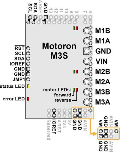
The diagram above identifies the control and power pins on the Motoron M3S550 and M3S256. Pins that are used by the motor controller are indicated in black, while pins that are not connected to anything by default are gray (these mostly serve as extra access points for the Arduino’s pins if the Motoron is plugged in as a shield). Section 3.2.3 explains how to connect motor power, motors, and a microcontroller.
The motor power supply should be connected to the VIN pin and adjacent GND pin, and a motor can be connected to each pair of MxA and MxB pins (e.g. M1A and M1B). For more information on choosing a power supply and motors, see Section 3.1.
The Motoron’s logic is powered from the Arduino by the IOREF pin. On the Motoron M3S256, the Motoron’s logic voltage (which powers its microcontroller) comes directly from IOREF. On the Motoron M3S550, the IOREF pin supplies power to a 3.3 LDO regulator, and the output of that regulator powers the Motoron’s microcontroller and is called the logic voltage.
The Motoron is controlled via I²C through the SCL and SDA pins (see Section 6). Additional GND pins provide a common ground reference between the Motoron and Arduino.
The JMP1 pin can be shorted to the adjacent GND pin to allow the Motoron’s I²C address to be changed, as detailed in Section 3.5. Also, shorting JMP1 to GND at startup causes the Motoron to ignore the address configured in EEPROM and use 15 as its I²C address instead.
The RST pin can be driven low to reset the Motoron; see Section 12 for more details.
Powering the Arduino
The VM pins near the lower right corner of the board provide access to the reverse-protected motor supply voltage. VM can optionally be used to power the Arduino’s VIN pin (AVIN) either directly or through a regulator.
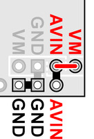
If the voltage of your motor power supply is within the allowed input voltage range for your Arduino, then you can power the Arduino by connecting the Motoron’s AVIN pin to the nearby VM pin. Doing this supplies power to Arduino’s VIN pin (AVIN) from the reverse-protected motor supply voltage (VM).
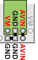
Alternatively, you can power the Arduino through a voltage regulator. The Motoron M3S550 and M3S256 have VM, GND, and AVIN pins next to each other which are designed to be connected to a regulator. The regulator should be connected in the correct orientation so that the Motoron’s VM pin is connected to the regulator’s power input and the regulator’s power output is connected to AVIN. The motor power supply must be in the allowed input voltage range of the regulator, and the regulator must produce an output voltage that is within the allowed input voltage range of the Arduino. The regulator must also be able to supply enough current for the Arduino.
To avoid shorting two power outputs together, do not connect anything to the Arduino’s DC power jack while supplying power to AVIN through the Motoron.
|
|


