Support » Pololu Motoron Motor Controller User’s Guide » 4. Pinout »
4.1. Motoron M1T550, M2T550, M1T256 and M2T256 pinout
|
|
||||
|
|
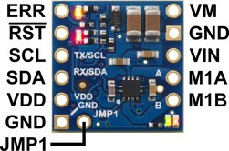
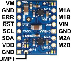
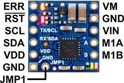
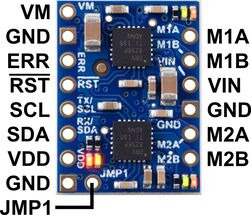
The diagrams above identify the control and power pins on the Motoron M1T550, M2T550, M1T256 and M2T256. Section 3.2.1 explains how to connect motor power, motors, and a microcontroller.
The motor power supply should be connected to the VIN pin and adjacent GND pin, and a motor can be connected to each pair of MxA and MxB pins (e.g. M1A and M1B). For more information on choosing a power supply and motors, see Section 3.1.
The Motoron’s logic is powered from the VDD pin, and it is controlled via I²C through the SCL and SDA pins (see Section 6). Additional GND pins provide a common ground reference between the Motoron and device controlling it.
The VM pin provides access to the reverse-protected motor supply voltage.
The ERR pin drives high when the red LED is on, which usually indicates an error as described in Section 5. The ERR pin is protected by a 220Ω series resistor. When the red LED is not on, the ERR pin is pulled down weakly.
The RST pin can be driven low to reset the Motoron; see Section 12 for more details.
The JMP1 pin can be shorted to the adjacent GND pin to allow the Motoron’s I²C address to be changed, as detailed in Section 3.5. Also, shorting JMP1 to GND at startup causes the Motoron to ignore the address configured in EEPROM and use 15 as its I²C address instead.


