Support » Pololu RC Switch User’s Guide » 2. RC Switch with Digital Output »
2.2. Connecting the RC Switch with Digital Output
The typical way to connect the Pololu RC Switch with Digital Output is shown in the diagram below:
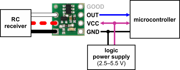 |
Typical wiring diagram for the Pololu RC Switch with Digital Output. |
|---|
The RC switch can be plugged directly into an RC receiver or servo controller using a Female-Female servo extension cable. These can be found in our Servo Cables category. The switch will read the signal from the RC receiver, but in the default configuration it will not draw or supply any power to the receiver, so the power wire is optional. The receiver will need its own power source.
Power for the switch’s logic needs to be applied to GND and VCC and must be between 2.5 V and 5.5 V. Many microcontroller boards have a 3.3 V or 5 V line that powers the microcontroller and would also be suitable for powering the RC switch.
The OUT line can be connected to a digital input pin on the microcontroller.
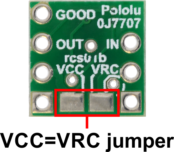
Power jumper
The setup described above involves two separate power supplies. For some applications, this setup can be simplified by bridging the VCC=VRC power jumper on the bottom of the board. This allows you to either power the microcontroller and RC switch from the RC receiver’s power supply or to power the RC receiver and RC switch from the microcontroller’s power supply.
 |
Related products


Home | Forum | Blog | Support | Ordering Information | Wish Lists | Distributors | BIG Order Form | About | Contact
© 2001–2024 Pololu Corporation
