Support » Pololu A-Star 328PB User’s Guide »
1. Overview
 |
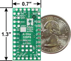
A-Star 328PB Micro, bottom view with dimensions. |
|---|
The Pololu A-Star 328PB Micro is a general-purpose programmable module based on the ATmega328PB AVR microcontroller, which has 32 KB of flash program memory and 2 KB of RAM. The ATmega328PB is a backward-compatible, improved replacement for the popular ATmega328P found on other programmable modules like our Baby Orangutan B-328 and the Arduino Uno and Pro Mini, so programs written for those other boards will generally work on the A-Star 328PB Micro with appropriate adjustments for any differences in clock speed. On-board features of the A-Star (abbreviated A*) include a resonator, user and power LEDs, and a reset button. The board includes a low-dropout linear voltage regulator that allows it to be powered from external supplies up to 15 V, and reverse voltage protection on this main power input helps safeguard against accidental damage. The board can also be powered through its TTL serial header by a USB-to-serial adapter, and an integrated power switching circuit makes it safe to have both supplies connected at the same time.
The A-Star 328PB Micro breaks out 19 general-purpose I/O lines along two rows of pins, including seven usable as PWM outputs and eight usable as analog inputs; another five GPIO pins (including two usable as PWM outputs) can be accessed along the bottom edge of the board. It provides both an in-system programming (ISP) header and a connector for TTL serial programming along the top edge. The board fits all this into a 1.3″ × 0.7″ area (the same size as the Arduino Pro Mini), and its 0.1″ pin spacing makes the A* easy to use with solderless breadboards, perfboards, and 0.1″-pitch connectors.
The A-Star 328PB Micro is available in four logic voltage and resonator frequency combinations:
- 5 V, 16 MHz (blue power LED)
- 5 V, 20 MHz (red power LED) Note: See speed warning below.
- 3.3 V, 8 MHz (green power LED)
- 3.3 V, 12 MHz (yellow power LED)
Each of the four versions uses a different power LED color as a way to differentiate them.
Speed warning for 20 MHz version: The 20 MHz resonator frequency exceeds the maximum explicitly allowed in the ATmega328PB datasheet. In our basic testing, the 20 MHz resonator appears to function without problems, but for any critical applications you should confirm for yourself that this product is appropriate.
Either a USB-to-serial adapter or an AVR in-system programmer (ISP) is required to program the A-Star 328PB Micro from a computer. We recommend our USB AVR Programmer v2.1, which can be used as both, and can be configured to run at either 3.3 V or 5 V.
Features
- Dimensions: 1.3″ × 0.7″
- Programmable ATmega328PB AVR microcontroller
- 32 KB flash (0.5 KB used by bootloader, leaving 31.5 KB available for user program by default)
- 2 KB SRAM
- 1 KB EEPROM
- All I/O lines from the ATmega328PB broken out in a compact package
- 19 general-purpose I/O pins available along the sides of the board
- 5 additional I/O pins available on bottom edge
- 9 pins can be configured as hardware PWM outputs (7 along sides of board)
- 8 pins can be configured as analog inputs
- Preloaded with Arduino-compatible TTL serial bootloader
- 6-pin TTL serial programming header for use with a USB-to-serial adapter (we recommend our USB AVR Programmer v2.1, which can act as a USB-to-serial adapter)
- 6-pin ISP header for use with an external AVR programmer (we recommend our USB AVR Programmer v2.1)
- Power LED and user-controllable LED
- Reset button
- Two power options:
- 3.8 V to 15 V (3.3 V versions) or 5.5 V to 15 V (5 V versions) on BAT+
- USB-to-serial adapter can supply power to VCCIN on the serial header
- Reverse-voltage protection on BAT+ supply
Differences between the ATmega328P and ATmega328PB
Compared to the ATmega328P (and ATmega328), the ATmega328PB microcontroller offers a number of improvements, including:
- Two additional GPIO pins: PE0 and PE1
- Two pins that were previously analog inputs only (ADC6 and ADC7) can now also be used as digital inputs and outputs: PE2 and PE3
- Two additional 16-bit Timer/Counters: TC3 and TC4 (for a total of two 8-bit timers and three 16-bit timers)
- Three additional PWM output pins
- A second USART (TTL serial port)
- A second TWI (Two-Wire Serial Interface, I²C-compatible)
- A second SPI (Serial Peripheral Interface)
- A peripheral touch controller (PTC) for adding capacitive touch buttons, sliders, and wheels
The ATmega328PB is code-compatible with the ATmega328P, meaning code compiled for an ATmega328P will run as intended on an ATmega328PB. This application note (283k pdf) by Atmel (now part of Microchip) comprehensively describes the differences between the ATmega328PB and its predecessors.
Our Arduino software add-on makes it easy to use the additional GPIO functionality, PWM outputs, and TTL serial port. The other new features of the ATmega328PB can still be used from the Arduino environment through direct register access or custom libraries.
The A-Star family
 |
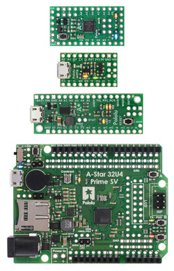
From top to bottom: A-Star 328PB Micro, 32U4 Micro, 32U4 Mini SV, and 32U4 Prime SV. |
|---|
The A-Star 328PB Micro is a part of our larger A-Star family, all of whose members are based on AVR microcontrollers and are preloaded with Arduino-compatible bootloaders. The table below shows some key features and specifications of our A-Star microcontroller boards to help you choose the right one for your application.
 |
 |
   |
  |
  | |
|---|---|---|---|---|---|
| A-Star 328PB Micro | A-Star 32U4 Micro | A-Star 32U4 Mini ULV A-Star 32U4 Mini LV A-Star 32U4 Mini SV |
A-Star 32U4 Prime LV A-Star 32U4 Prime SV |
A-Star 32U4 Robot Controller LV A-Star 32U4 Robot Controller SV |
|
| Microcontroller: | ATmega328PB | ATmega32U4 | |||
| User I/O lines: | 24 | 18 | 26 | 26(1) | 26(1) |
| Available PWM outputs: | 9 | 6 | 7 | 7 | 7(1) |
| Analog inputs: | 8 | 8 | 12 | 12 | 12(1) |
| Ground access points: | 6 | 2 | 4 | 43 | 44 |
| User LEDs: | 1 | 2 | 3 | 3 | 3 |
| User pushbuttons: | — | — | — | 3 | 3 |
| USB interface: |  |
 |
 |
 |
|
| Reset button: |  |
 |
 |
 |
|
| Power switch: |  |
 |
|||
| Buzzer option: |  |
 |
|||
| microSD option: |  |
||||
| LCD option: |  |
||||
| Motor drivers: |  |
||||
| Operating voltage: | 3.3V VCC: 3.8 V to 15 V 5V VCC: 5.5 V to 15 V |
5.5 V to 15 V | ULV: 0.5 V to 5.5 V LV: 2.7 V to 11.8 V SV: 5 V to 40 V |
LV: 2 V to 16 V SV: 5 V to 36 V |
LV: 2.7 V to 11 V SV: 5.5 V to 36 V |
| Regulator type: | 3.3 V or 5 V linear | 5 V linear | 5 V switching ULV: step-up LV: step-up/step-down SV: step-down |
5 V switching LV: step-up/step-down SV: step-down |
5 V switching LV: step-up/step-down SV: step-down |
| Regulated current:(2) | 100 mA | 100 mA | ULV: 500 mA LV: 1 A SV: 800 mA |
LV: 1.8 A SV: 1 A |
LV: 1 A SV: 1.5 A |
| Dimensions: | 1.3″ × 0.7″ | 1″ × 0.6″ | 1.9″ × 0.7″ | 2.8″ × 2.1″ | 2.6″ × 2.2″ |
| Weight: | 1.5 g(3) | 1.3 g(3) | 3.4 g(3) | 13 g to 33 g | 14 g to 23 g |
| Price: | $11.72 | $19.95 | $29.95 to $29.95 | $33.40 to $53.00 | $39.05 to $54.84 |
| 1 Some microcontroller resources are used by on-board hardware. | |||||
| 2 These values are rough approximations for comparison purposes. Available current depends on input voltage, current consumed by the board, ambient conditions, and regulator topology. See product documentation and performance graphs for details. | |||||
| 3 Without included optional headers. | |||||


