Support »
Pololu USB AVR Programmer v2 User’s Guide
View document on multiple pages.
You can also view this document as a printable PDF.
- 1. Overview
- 2. Contacting Pololu
- 3. Pinout and components
- 4. Getting started
- 5. AVR programming
- 5.1. Connecting an AVR for programming
- 5.2. AVR programming using Microchip Studio
- 5.3. AVR programming using AVR Studio 4
- 5.4. AVR programming using the Arduino IDE
- 5.5. AVR programming using AVRDUDE
- 5.6. Troubleshooting AVR programming issues
- 5.7. Programming faster
- 5.8. Reading and writing from EEPROM and flash
- 5.9. Setting fuses and lock bits
- 5.10. Using the clock output to revive AVRs
- 6. USB-to-TTL serial adapter
- 7. Power settings and status
- 8. Using VCC or VBUS to supply power
- 9. Upgrading firmware
1. Overview
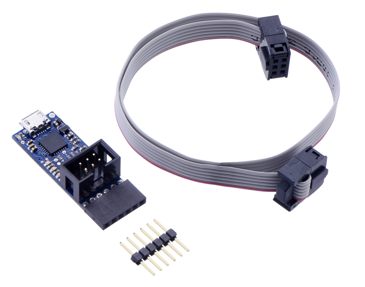 |
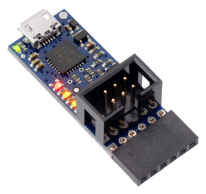
Pololu USB AVR Programmer v2 or v2.1 with included hardware. |
|---|
The Pololu USB AVR Programmer v2 and the Pololu USB AVR Programmer v2.1 are compact, low-cost in-system programmers (ISP) for AVR microcontrollers from Atmel (now a part of Microchip). The programmer provides an interface for transferring a compiled AVR program from your computer to the target AVR’s flash memory, allowing it to run the program. It is a good solution for programming AVR-based controllers like our A-Star 328PB Micro and Orangutan robot controllers. It can also be used to update, replace, or remove the bootloader on Arduino boards and our Arduino-compatible A-Star 32U4 controllers. This programmer is designed to work well with both 3.3 V and 5 V devices, and it can even be configured to provide power to the target device in low-power systems.
This guide covers both the Pololu USB AVR Programmer v2 (Pololu item #3170) and the Pololu USB AVR Programmer v2.1 (Pololu item #3172). Unless otherwise specified, the information in this guide applies to both versions. This guide often uses the designation “Pololu USB AVR Programmer v2.x” to refer to both versions at the same time. Many of the pictures in this user’s guide show a specific version of the programmer, but both versions have the same size and pinout, so you can refer to the pictures to learn about your programmer even if you have a different version from what is shown.
Features and specifications
- Connects to a computer through USB via a USB A to Micro-B cable (not included)
- Emulates an STK500 programmer through virtual COM port interface
- Works with standard AVR programming software, including Microchip Studio (Atmel Studio), AVRDUDE, and the Arduino IDE
- Configuration software available for Windows, Mac OS X, and Linux
- Supports both 3.3 V and 5 V devices; can automatically switch operating voltage based on detected target VCC
- Can optionally power the target at 3.3 V or 5 V in low-power systems
- USB-to-TTL serial adapter functionality for general-purpose serial communication
- Provides a 100 kHz clock output, which can be useful for reviving misconfigured AVRs
- All I/O pins are protected with 470 Ω resistors
- 6-pin ISP cable and a 1×6 double-sided male header included
Distinguishing different Pololu programmers
If you have a blue programmer and you are not sure what version it is, look at the name printed on the bottom side. If you have a green programmer, refer to the pictures below.
Please note that this guide only applies to the Pololu USB AVR Programmer v2 (Pololu item #3170) and the Pololu USB AVR Programmer v2.1 (Pololu item #3172), which are both blue. If you have the original version of the Pololu USB AVR Programmer (Pololu item #1300), you can find its user’s guide here. If you have the Orangutan USB programmer (Pololu item #740), you can find its user’s guide here.
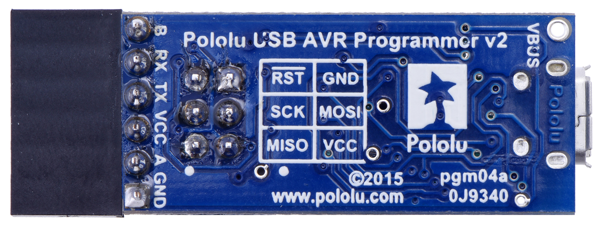 |
Pololu USB AVR Programmer v2, bottom view. |
|---|
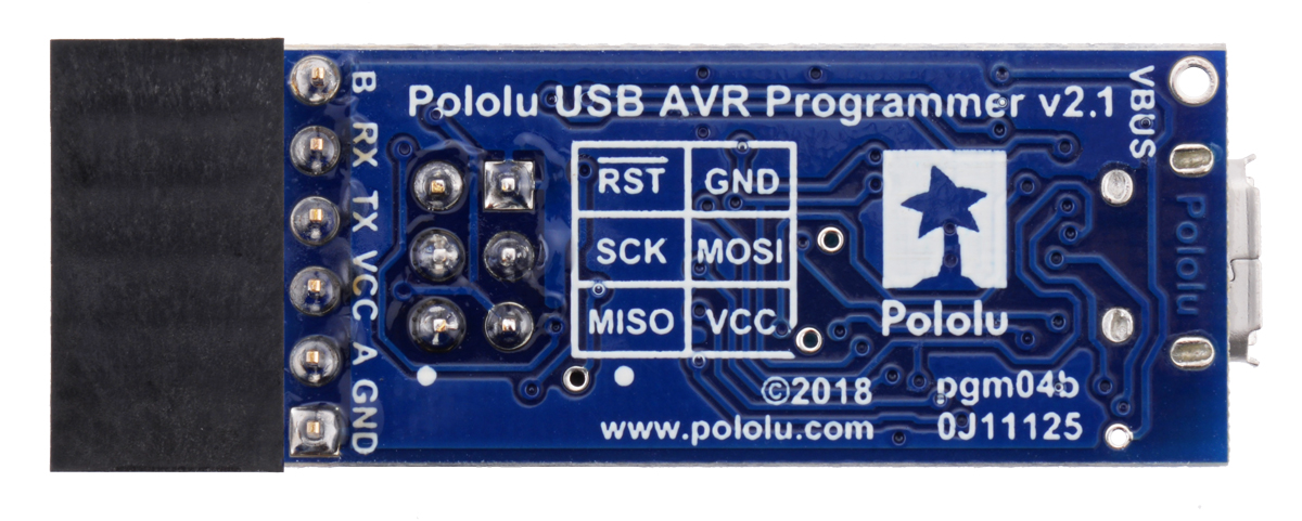 |
Pololu USB AVR Programmer v2.1, bottom view. |
|---|
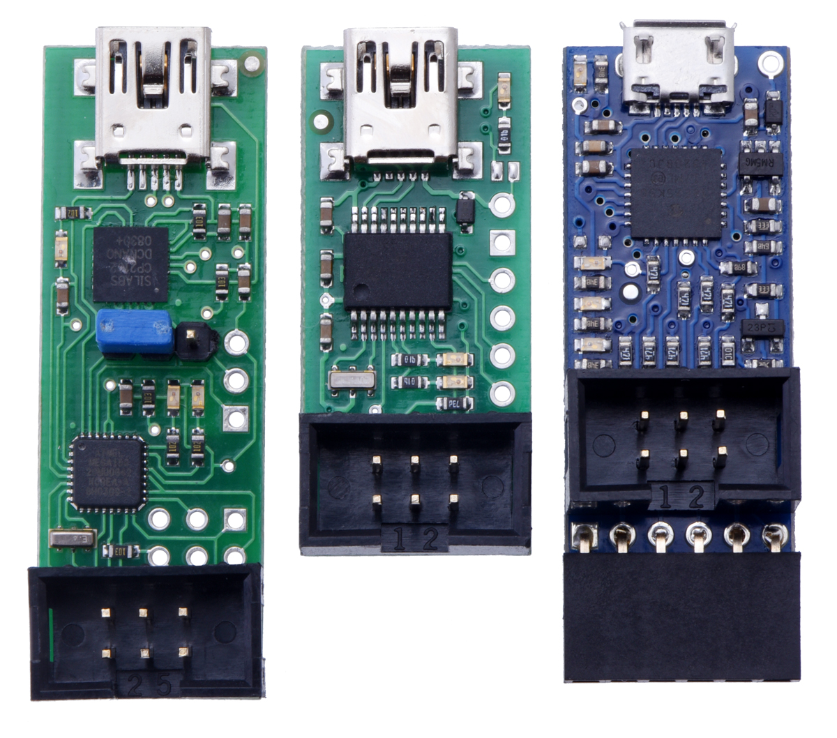 |
From left to right: the original Orangutan USB Programmer, the Pololu USB AVR Programmer, and the Pololu USB AVR Programmer v2 (which looks almost the same as v2.1). |
|---|
1.1. Supported AVR microcontrollers
The programmer should work with all AVRs that can be programmed with the AVR ISP (in-system programming) interface, which is also known as in-circuit serial programming (ICSP), serial programming, or serial downloading, but it has not been tested with all devices. We expect it to work with most AVRs in the megaAVR (ATmega) family. It does not work with the megaAVR 0-series of AVRs (e.g. the ATmega4809). This programmer works with some members of the tinyAVR (ATtiny) family, but it does not support the Tiny Programming Interface (TPI), and it does not support the Unified Program and Debug Interface (UPDI). It does not work with the XMEGA family or with 32-bit AVRs. The programmer features upgradable firmware, allowing updates for future devices.
The programmer is incompatible with some AVR boards that have extra components on their programming pins. The programmer’s I/O pins are protected by 470 Ω resistors, so pull-up or pull-down resistors on those lines that have a value below 5 kΩ might prevent the programmer from properly communicating with the AVR. For example, the programmer does not work with the Arduino Nano due to the 1 kΩ pull-up resistor on its reset line.
1.2. Supported operating systems
We support using the Pololu USB AVR Programmer v2.x and its configuration software on Windows 7, Windows 8, Windows 10, Windows 11, Linux, and macOS 10.11 or later. The programmer is not likely to work on Windows 10 IoT Core, which is very different from the normal desktop versions of Windows. We have tested the programmer and its software on Raspbian Jessie for the Raspberry Pi, so we expect it to work on that version of Raspbian and later versions.
2. Contacting Pololu
 |
We would be delighted to hear from you about any of your projects and about your experience with the Pololu USB AVR Programmer v2.x. You can contact us directly or post on our forum. Tell us what we did well, what we could improve, what you would like to see in the future, or anything else you would like to say!
3. Pinout and components
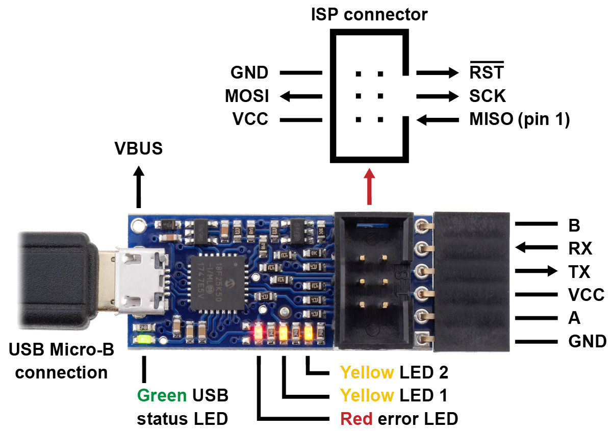 |
Pololu USB AVR Programmer v2.1, labeled top view. |
|---|
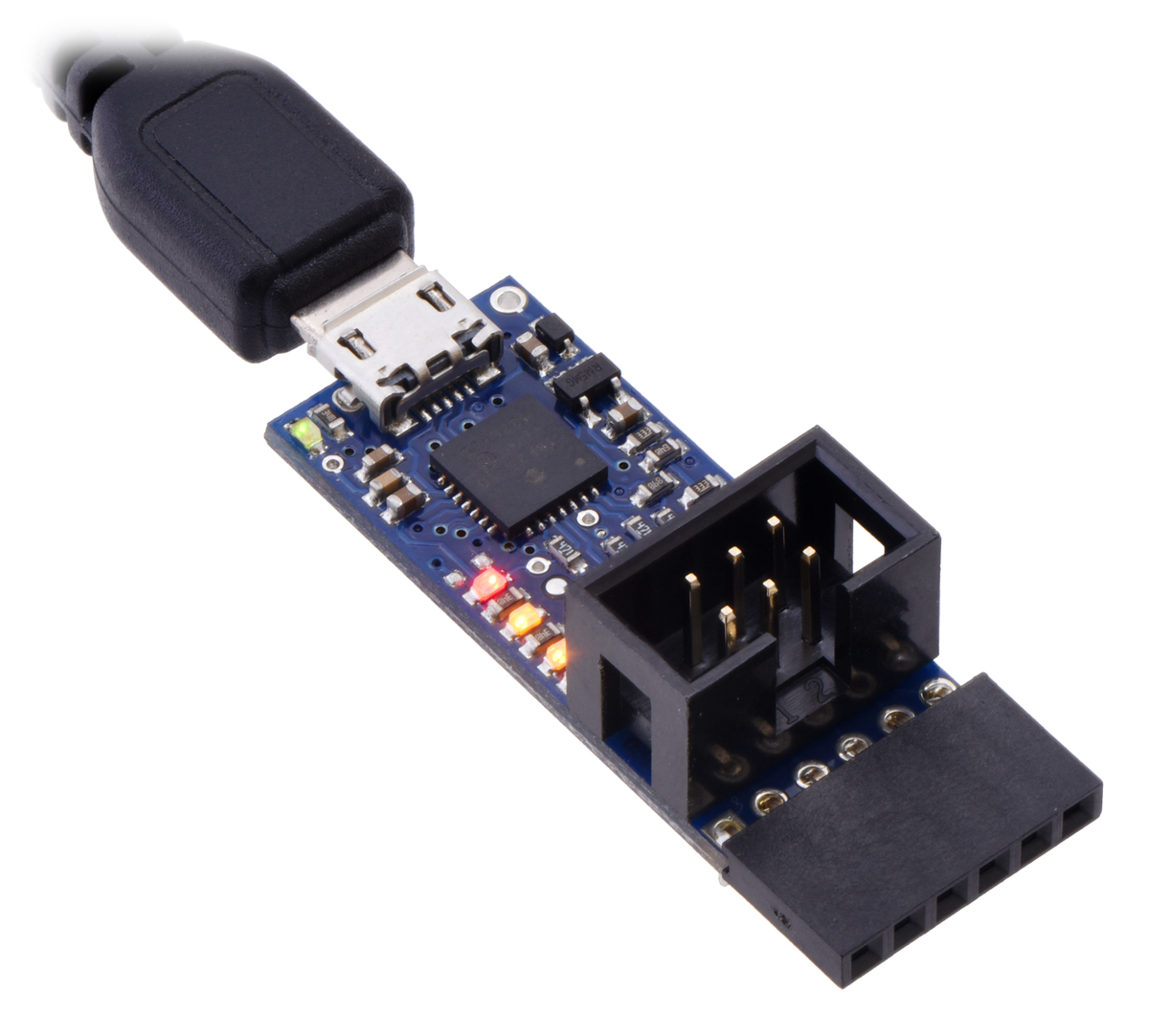
The Pololu USB AVR Programmer v2.x connects to a computer’s USB port via a USB A to Micro-B cable (not included).
The programmer has a standard 6-pin AVR ISP connector for programming AVRs. It connects to the target AVR device via an included 6-pin ISP cable. The cable has a keyed connector that matches the programmer’s shrouded header, making it impossible to plug the cable into the programmer in the wrong orientation. The older 10-pin ISP connections are not directly supported, but it is easy to create or purchase a 6-pin-to-10-pin ISP adapter. The six pins on the ISP connector are:
- MISO: The “Master Input, Slave Output” line for SPI communication with the target AVR. This is called PDO in some AVR datasheets. The programmer is the master, so this line is an input.
- VCC: By default, this line is an input that the programmer uses to measure the voltage of the target AVR (see Section 7). This line can also be configured to power the target device (see Section 8).
- SCK: The clock line for SPI communication with the target AVR. The programmer is the master, so this line is an output during programming.
- MOSI: The “Master Output, Slave Input” line for SPI communication with the target AVR. This is called PDI in some AVR datasheets. The programmer is the master, so this line is an output during programming.
- RST: The target AVR’s reset line. This line is used as an output driven low during programming to hold the AVR in reset.
- GND: Ground. This line should be connected to the target device’s ground.
When the programmer is not actively programming an AVR, the MISO, SCK, and MOSI pins are all high-impedance inputs.
The end of the programmer has a 6-pin serial header with a pinout that is similar to commonly-available FTDI cables and breakout boards. The programmer comes with a 6-pin right-angle female header soldered in. The six pins on this header are:
- GND: Ground. This is connected to the GND pin on the ISP header and the GND pin of the USB cable.
- A: By default, this line is just an input that is pulled up, but it can be configured to do serial control/handshaking functions (see Section 6.1).
- VCC: This is connected to the VCC pin on the ISP connector. By default it is an input, but it can be configured as an output for powering other devices (see Section 7 and Section 8).
- TX: This is a TTL serial output pin that can send data to another device (see Section 6.1).
- RX: This is a TTL serial input pin that can receive data from another device (see Section 6.1).
- B: By default, this line is configured to be the DTR (Data Terminal Ready) signal. It can be configured for other serial/handshaking functions (see Section 6.1) or it can be used as a clock output signal (see Section 5.10).
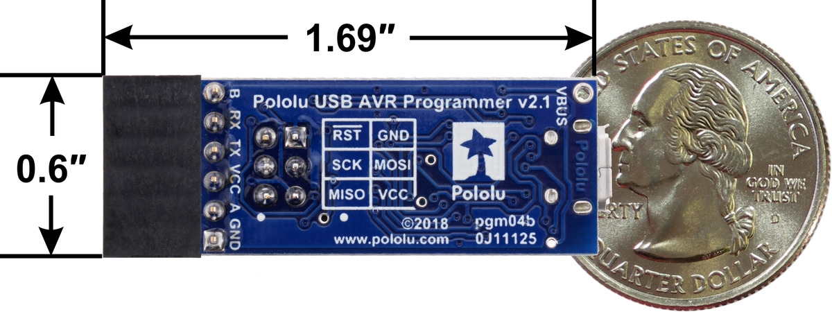 |
Pololu USB AVR Programmer v2.1, bottom view with dimensions. |
|---|
The programmer’s circuit board is 0.6″ wide and 1.35″ long. With the right-angle female header, it is about 1.69″ long.
The programmer has 4 LEDs that indicate its status. The behavior of these LEDs is described in detail in Section 4.4.
The VBUS line is connected directly to the USB cable’s 5V power supply line. It can be used to power external devices as long as you are careful not to draw too much current from it (see Section 8).
Included accessories
The Pololu USB AVR Programmer v2.x comes with the accessories shown in the picture below. The 6-pin ISP cable can be used to program AVRs. The 1×6 double-sided male header can be plugged into the serial header to effectively reverse its gender (making it possible to connect that header to a breadboard or female jumper wires). A USB A to Micro-B cable is required and not included.
|
Pololu USB AVR Programmer v2 or v2.1 with included hardware. |
|---|
4. Getting started
4.1. Installing Windows drivers and software
Please note that these drivers will only work for the v2.x versions of the Pololu USB AVR Programmer, not the original item #1300 Pololu USB AVR Programmer. If you have the original programmer, which has a green PCB instead of blue, you will need to install the drivers specific to that device.
The Pololu USB AVR Programmer v2.x has drivers and configuration software for Windows. The drivers tell Windows how to recognize the programmer and set it up correctly. The drivers are needed for Windows Vista, Windows 7, and Windows 8. For Windows 10 and later, the drivers are optional but recommended. The configuration software allows you to change the programmer’s settings and can be helpful for troubleshooting.
Before connecting your programmer to a computer running Microsoft Windows, we recommend installing its drivers and software by following these steps.
- Download and install the Pololu USB AVR Programmer v2 Software and Drivers for Windows (9MB msi). Please note that the drivers and software in this installer will only work with the Pololu USB AVR Programmer v2 and v2.1, which are blue-colored.
- During the installation, Windows will ask you if you want to install the drivers. Click “Install” to proceed.
- After the installation has finished, your computer should automatically set up the necessary drivers when you connect a Pololu USB AVR Programmer v2.x, in which case no further action from you is required.
After installing the drivers and plugging the programmer in via USB, if you go to your computer’s Device Manager, you should see three entries for the programmer as shown below:
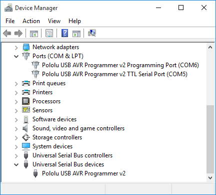 |
Windows 10 Device Manager showing the Pololu USB AVR Programmer v2 |
|---|
The programmer configuration software consists of two programs:
- The Pololu USB AVR Programmer v2 Configuration Utility is a graphical user interface (GUI) for configuring the programmer and viewing its status. You can find the configuration utility in your start menu by searching for it or looking in the Pololu folder.
- The Pololu USB AVR Programmer v2 Command-line Utility (pavr2cmd) is a command-line utility that can do everything that the GUI can do. You can open a terminal and type
pavr2cmdwith no arguments to a see a summary of its options.
COM ports
In the “Ports (COM & LPT)” category of your Device Manager, you should see two COM ports with names like “Pololu USB AVR Programmer v2.1 Programming Port” and “Pololu USB AVR Programmer v2.1 TTL Serial Port”.
You might see that the COM ports are named “USB Serial Device” in the Device Manager instead of having descriptive names. This can happen if you are using Windows 10 or later and you plugged the programmer into your computer before installing our drivers for it. In that case, Windows will set up your programmer using the default Windows serial driver (usbser.inf), and it will display “USB Serial Device” as the name for each port. The ports will be usable, but it will be hard to distinguish the ports from each other because of the generic name shown in the Device Manager. We recommend fixing the names in the Device Manager by right-clicking on each “USB Serial Device” entry, selecting “Update Driver Software…”, and then selecting “Search automatically for updated driver software”. Windows should find the drivers you already installed, which contain the correct name for the port.
If you are using Windows 10 or later and choose not to install the drivers, the programmer will still be usable. See Section 4.5 for information about determining which COM port is which.
If you want to change the COM port numbers assigned to your programmer, you can do so using the Device Manager. Double-click a COM port to open its properties dialog, and click the “Advanced…” button in the “Port Settings” tab. Windows will associate this COM port number with the USB serial number of your programmer and use it whenever you plug that programmer in. If you have multiple programmers but only plug in one at a time, it can be helpful to assign each programmer to the same set of COM ports.
Native USB interface
There should be an entry for the programmer in the “Universal Serial Bus devices” category with a name like “Pololu USB AVR Programmer v2.1”. This represents the programmer’s native USB interface, and it is used by our configuration software. The programmer’s native USB interface implements Microsoft OS 2.0 Descriptors, so it will work on Windows 8.1 or later without needing any drivers. The driver we provide is needed for earlier versions of Windows.
USB troubleshooting for Windows
If the software you are using cannot communicate properly with the programmer, a good first step is to just unplug it from everything and then plug it back in again.
You should also make sure you are specifying the right COM port name in your software. AVR programming software should usually connect to the programmer’s programming port. If you want to communicate using the RX and TX lines, you should connect to the TTL serial port. You can find the right COM port names by following the instructions in Section 4.5.
If that does not work, you should try to locate all the entries for the programmer in the Device Manager. Be sure to look in these categories: “Other devices”, “Ports (COM & LPT)” and “Universal Serial Bus devices”. It might help to click “View”, select “Devices by Connection”, and then expand entries until you can find entries relating to the programmer. When viewing devices by connection, the programmer is normally represented by a “USB Composite Device” entry that has three child entries which should look like the entries shown in the screenshot above. Any entry corresponding to the programmer might have an incorrect name if the wrong driver is installed or there was an error. You can tell if an entry corresponds to the programmer by unplugging the programmer and checking to see whether the entry disappears. Finding the programmer’s entries in the Device Manager can often give you a good idea of what is wrong.
If the programmer has no entries in your Device Manager, you probably have a low-level hardware problem. Try using a different USB cable and a different USB port. Make sure your cable is not a charging-only cable.
If the programmer does have entries in the Device Manager, but they don’t look like the screenshot above, then you might have a driver installation problem. To ask Windows to use the right drivers, you can right-click on each entry, select “Update Driver Software…”, select “Browse my computer for driver software”, and then enter the location of the “drivers” folder for the programmer. This is typically “C:\Program Files (x86)\Pololu\USB AVR Programmer v2\drivers”.
Do not attempt to fix driver issues in your Device Manager using the “Add legacy hardware” option. This is only for older devices that do not support Plug-and-Play, so it will not help. If you already tried this option, we recommend unplugging the programmer from USB and then removing any entries you see for the programmer by right-clicking on them and selecting “Uninstall”. Do not check the checkbox that says “Delete the driver software for this device”.
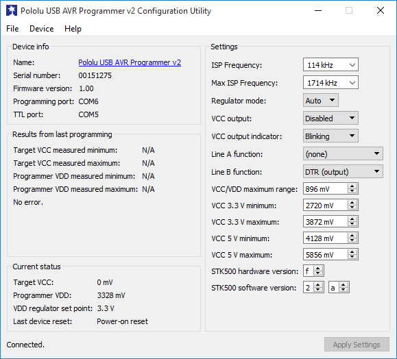 |
The Pololu USB AVR Programmer v2 Configuration Utility in Windows 10. |
|---|
4.2. Installing Linux software
To install the software for the Pololu USB AVR Programmer v2.x on a computer running Linux, follow these steps:
- Download the version for your system from this list:
- Pololu USB AVR Programmer v2 Software for Linux (x86) (8MB xz) — works on 32-bit and 64-bit systems
- Pololu USB AVR Programmer v2 Software for Linux (Raspberry Pi) (6MB xz) — works on the Raspberry Pi and might work on other ARM Linux systems
- In a terminal, use
cdto navigate to the directory holding the downloaded file. For example, runcd ~/Downloadsif it was downloaded to the “Downloads” folder in your home directory. - Run
tar -xvf pololu-usb-avr-programmer-v2-*.tar.xzto extract the software. If you downloaded multiple versions of the software, you should use an exact file name instead of an asterisk. - Run
sudo pololu-usb-avr-programmer-v2-*/install.shto install the software. You will need to have sudo privilege on your system and you might need to type your password at this point. Look at the output of the script to see if any errors happened. - After the installation has completed, plug the programmer into your computer via USB. If you already connected the programmer earlier, unplug it and plug it in again to make sure the newly-installed udev rules are applied.
- Run
pavr2cmd --listto make sure the software can detect the programmer. This command should print the serial number and product name of the programmer. If it prints nothing, see the “USB troubleshooting for Linux” section below. - Run
pavr2guito start the configuration utility.
The programmer does not require any driver installation on Linux. The Linux kernel’s cdc_acm module creates entries for the programmer’s virtual serial ports with names like /dev/ttyACM0 and /dev/ttyACM1 so that they can be used by software, and other parts of Linux allow access to the programmer’s native USB interface. For more information about determining the names assigned to the programmer’s virtual serial ports, see Section 4.5.
This programmer configuration software consists of two programs:
- The Pololu USB AVR Programmer v2 Configuration Utility (pavr2gui) is a graphical user interface (GUI) for configuring the programmer and viewing its status. You can open a terminal and type
pavr2guito run it. - The Pololu USB AVR Programmer v2 Command-line Utility (pavr2cmd) is a command-line utility that can do everything that the GUI can do. You can open a terminal and type
pavr2cmdwith no arguments to a see a summary of its options.
The programmer’s configuration software for Linux is statically compiled; it does not depend on any shared libraries. The source code for the software is available.
Software installation troubleshooting for Linux
If you do not have sudo privilege or you do not remember your password, you can skip running install.sh and just run the programs directly from the directory you extracted them to. You should also consider moving the software to a more permanent location and adding that location to your PATH as described below.
If you get a “No such file or directory” error while running ./install.sh, it is possible that your system is missing one of the directories that the install script assumes will be present. Please contact us to let us know about your system so we can consider supporting it better in the future.
If you get the error “command not found” when you try to run pavr2cmd or pavr2gui, then you should run echo $PATH to see what directories are on your PATH, and then make sure one of those directories contains the programmer executables or symbolic links to them. The installer puts symbolic links in /usr/local/bin, so if that directory is not on your PATH, you should run export PATH=$PATH:/usr/local/bin to add it. Also, you might want to put that line in your ~/.profile file so the directory will be on your PATH in future sessions.
If you get the error “cannot execute binary file: Exec format error” when you try to run pavr2cmd or pavr2gui, then it is likely that you downloaded the wrong version of the software from the list above. If all of the listed versions give you this error, you will probably need to compile the software from source by following the instructions in BUILDING.md in the source code. Please contact us to let us know about your system so we can consider supporting it better in the future.
If the text in the configuration utility window is not visible, make sure that the .ttf font file that we ship with the software is in the same directory as the pavr2gui executable.
USB troubleshooting for Linux
If the programmer’s configuration software cannot connect to your programmer after you plug it into the computer via USB, the tips here can help you troubleshoot the programmer’s USB connection.
If you have connected any electronic devices to your programmer besides the USB cable, you should disconnect them.
You should look at the LEDs of the programmer. If the LEDs are off, then the programmer is probably not receiving power from the USB port. If the green LED is flashing very briefly once per second, then the programmer is receiving power from USB, but it is not receiving any data. These issues can be caused by using a broken USB port, using a broken USB cable, or by using a USB charging cable that does not have data wires. Using a different USB port and a different USB cable, both of which are known to work with other devices, is a good thing to try. Also, if you are connecting the programmer to your computer via a USB hub, try connecting it directly.
If the programmer’s green LED is on all the time or flashing slowly, but you can’t connect to it in the programmer’s configuration software, then there might be something wrong with your computer. A good thing to try is to unplug the programmer from USB, reboot your computer, and then plug it in again.
If you get a “Permission denied” error when trying to connect to the programmer, you should make sure to copy the 99-pololu.rules file into /etc/udev/rules.d and then unplug the programmer and plug it back in again. The install script normally takes care of installing that file for you.
If that does not help, you should try running lsusb to list the USB devices recognized by your computer. Look for the Pololu vendor ID, which is 1ffb. You should also try running dmesg right after plugging in the programmer to see if there are any messages about it.
4.3. Installing macOS software
To install the configuration software for the Pololu USB AVR Programmer v2.x on a computer running macOS, follow these steps:
- Download the Pololu USB AVR Programmer v2 Software for Mac OS X (7MB pkg).
- Double-click on the downloaded file to run it, and follow the instructions.
The programmer does not require any driver installation on Mac OS X. The AppleUSBCDCACM driver that comes with the operating system creates entries for the programmer’s serial ports with names like /dev/cu.usbmodem00022331 so that they can be used by software, and other parts of Mac OS X allow access to the programmer’s native USB interface. For more information about determining the names assigned to the programmer’s virtual serial ports, see Section 4.5.
The programmer’s configuration software consists of two programs:
- The Pololu USB AVR Programmer v2 Configuration Utility is a graphical user interface (GUI) for configuring the programmer and viewing its status. You can run the configuration utility by clicking on “Pololu USB AVR Programmer v2” in your computer’s Appllications folder.
- The Pololu USB AVR Programmer v2 Command-line Utility (pavr2cmd) is a command-line utility that can do everything that the GUI can do. You can open a Terminal and type
pavr2cmdwith no arguments to a see a summary of its options.
Software installation troubleshooting for macOS
If you get the error “command not found” when you try to run pavr2cmd or pavr2gui, then you should try starting a new Terminal window. The installer for the programmer’s software adds a file named 99-pololu-pavr2 in the /etc/paths.d directory to make sure the software gets added to your PATH, but the change will not take effect until you open a new Terminal window.
The programmer’s configuration software only works on macOS 10.11 or later.
USB troubleshooting for macOS
If the programmer’s configuration software cannot connect to your programmer after you plug it into the computer via USB, the tips here can help you troubleshoot the programmer’s USB connection.
If you have connected any electronic devices to your programmer besides the USB cable, you should disconnect them.
You should look at the LEDs of the programmer. If the LEDs are off, then the programmer is probably not receiving power from the USB port. If the green LED is flashing very briefly once per second, then the programmer is receiving power from USB, but it is not receiving any data. These issues can be caused by using a broken USB port, using a broken USB cable, or by using a USB charging cable that does not have data wires. Using a different USB port and a different USB cable, both of which are known to work with other devices, is a good thing to try. Also, if you are connecting the programmer to your computer via a USB hub, try connecting it directly.
If the programmer’s green LED is on all the time or flashing slowly, but you can’t connect to it in the software, then there might be something wrong with your computer. A good thing to try is to unplug the programmer from USB, reboot your computer, and then plug it in again.
Another thing to try is to run dmesg right after plugging in the programmer to see if there are any messages about it.
4.4. LED feedback
|
Pololu USB AVR Programmer v2.1, labeled top view. |
|---|
The Pololu USB AVR Programmer v2.x has four LEDs to indicate its status.
Most of the information provided by the LEDs is also available in the programmer’s configuration software. To see the programmer’s current status, just start the Pololu USB AVR Programmer v2 Configuration Utility or run pavr2cmd -s from a command prompt. However, learning the LED behavior can be helpful if you want to quickly make sure that the programmer is in the right state before using it.
The green LED indicates the USB status of the device. When you connect the programmer to the computer via the USB cable, the green LED will start blinking slowly. The blinking continues until the programmer gets a particular message from the computer that indicates that the programmer is recognized. After the programmer gets that message, the green LED will be on, but it will flicker briefly when there is USB activity. During suspend mode (e.g. while the computer is sleeping or while USB is disconnected and the programmer is inadvertently powered through its VCC pin), the green LED will be off but blink briefly every second to indicate that the programmer is powered but sleeping.
The red LED indicates an error or warning. When it is blinking, it means that the target AVR’s VCC power line is outside of the acceptable range. The red LED will blink about once per second, and the blinks will last about one half second (512 ms). When the red LED is on solid, it means that the last attempt at programming resulted in an error. You can determine the source of the error by running the programmer’s configuration software. If the target’s VCC line goes out of the acceptable range, the red LED will go back to blinking and no longer display the previous error even if target power is restored.
The two yellow LEDs indicate information about the programmer’s regulator mode, the current operating voltage of the programmer, and whether VCC is an output or not. More information about these settings can be found in the Power monitoring and regulator settings section and the Using VCC or VBUS to supply power section.
If VCC is configured to be an input (which is the default setting), the yellow LEDs behave as described below:
- If the programmer’s regulator mode is Auto (which is the default and means that it will automatically switch between 3.3 V and 5 V), and no power is currently detected on the target’s VCC line, then both yellow LEDs will be off. This is the default state of the programmer if you just plug it into a computer without changing any settings or connecting anything else. The red LED will be blinking because the target power is not detected.
- If the programmer’s regulator mode is 3.3 V (meaning that it always operates at 3.3 V), but the power on the the target’s VCC line is not within the acceptable range, then yellow LED 1 will blink once per second. Yellow LED 1 turns on a little bit (128 ms) after the red LED turns on, and turns off at the same time as the red LED. This blinking pattern is also used if the programmer’s regulator mode is Auto, and the programmer is currently operating at 3.3 V, but the voltage on the target’s VCC line is above the acceptable range.
- If the programmer is currently operating at 3.3 V and the target’s VCC level is within the acceptable range, then yellow LED 1 will blink briefly (64 ms) once per second.
- If the programmer’s regulator mode is 5 V (meaning that it always operates at 5 V), but the power on the target’s VCC line is not within the acceptable range, then both yellow LEDs will blink once per second. Yellow LED 1 turns on a little bit (128 ms) after the red LED turns on. Yellow LED 2 turns on a little bit (128 ms) after yellow LED 1. Both yellow LEDs turn off at the same time as the red LED. This blinking pattern is also used if the programmer’s regulator mode is Auto, and the programmer is currently operating at 5 V, but the voltage on the target’s VCC line is not within the acceptable range.
- If the programmer is currently operating at 5 V and the target’s VCC level is within the acceptable range, then both yellow LEDs will blink briefly (64 ms) once per second. Yellow LED 2 will blink a little bit after yellow LED 1 blinks.
If VCC is configured to be a 3.3 V output, then yellow LED 1 will blink eight times per second to warn you. If VCC is configured to be a 5 V output, then both yellow LEDs will blink eight times per second to warn you. If you want VCC to be an output but you do not want to see the yellow LEDs blinking so fast, you can change the “VCC Output Indicator” setting from “Blinking” to “Steady” using the configuration software. This makes the yellow LEDs just stay on solid instead of blinking eight times per second.
Note that the LED blinking patterns described above are not directly affected by measurements of the programmer’s actual operating voltage (VDD). In the descriptions above, a phrase like “operating at 3.3 V” just means that the programmer is trying to operate at that voltage.
To ensure that the programmer shows a complete blinking pattern instead of switching quickly between two or more patterns, the yellow LED blinking pattern is only updated once per second. So if you make a change to your system, you might have to wait for up to one second to see the LEDs respond.
The LEDs will be noticeably brighter when the programmer is operating at 5 V as opposed to 3.3 V.
Startup blinking
When the programmer starts running, it tries to detect if it was reset by some special condition. You can see the cause of the last reset in the configuration software’s “Last device reset” field, so it is usually easiest to just look there to diagnose any problem you are having with the programmer getting reset. The programmer also provides LED feedback to indicate why it was reset. If the programmer was reset by anything other than a standard power-on reset (which happens whenever power is turned on), the programmer will blink the red LED and/or yellow LED 1 in a special way for a second before it starts operating. The way these LEDs blink depend on the cause of the reset:
- If a brown-out reset occurred, the red LED will blink four times while the yellow LEDs stay off. A brownout-reset can happen if VCC is configured as an output and you are trying to power a device that has too much capacitance or draws to much current, as described in Section 8.
- If the programmer was reset by the reset line on its microcontroller, yellow LED 1 will blink four times while the red LED stays off. This should almost never happen.
- If the programmer was reset by its watchdog timer, then the red LED and yellow LED 1 will blink together four times. This is the expected behavior if the programmer was in bootloader mode and then received the USB command to quit the bootloader and start running the firmware.
- If any other type of non-standard reset happens, then the red LED will be on solid while yellow LED 1 blinks four times.
Bootloader mode
In bootloader mode, which is used for updating the firmware of the programmer itself and should only rarely be needed, the LEDs behave differently. The green LED still indicates the USB status, but it is different: after the programmer gets a particular message from the computer that indicates that the programmer is recognized, the green LED will start doing a double blinking pattern every 1.4 seconds. The yellow LED will usually be on solid, but it will blink quickly whenever a USB command is received. The red LED will be on if and only if there is no firmware currently loaded on the device.
4.5. Determining serial port names
The USB interface of the Pololu USB AVR Programmer v2.x provides two virtual serial ports: the programming port and the TTL serial port. To use either of these serial ports, you will usually have to know the name assigned to the serial port by the operating system (e.g. “COM6”).
The easiest way to find the serial port names is to run the configuration software we provide. You can run the Pololu USB AVR Programmer v2 Configuration Utility and look in the upper left corner to see the serial port names. In a command prompt, you can run pavr2cmd -s to see the port names. With either of these two methods, a port name will be displayed as “(unknown)” if it cannot be determined.
You can also run pavr2cmd --prog-port or pavr2cmd --ttl-port in a command prompt. Each of these commands simply prints the name assigned to the corresponding serial port. These commands are useful if you want to write a script that connects to one of the programmer’s serial ports but you do not know ahead of time what name it will have. These commands will print an error message on the standard error pipe if anything goes wrong.
In Windows, you can also determine the COM port names by looking in the Device Manager. Usually, both ports will be displayed in the “Ports (COM & LPT)” category. The descriptive name of the port (e.g. “Pololu USB AVR Programmer v2 Programming Port”) will be displayed, followed by the COM port name in parentheses. If the descriptive name is just “USB Serial Device” for both of the programmer’s ports, then you can identify the two ports by double-clicking on each one and looking at the “Hardware Ids” property in the “Details” tab. The programming port will have the ID USB\VID_1FFB&PID_00B0&MI_01, while the TTL serial port will have the ID USB\VID_1FFB&PID_00B0&MI_03. If you have trouble finding the ports in the Device Manager, see the USB driver troubleshooting tips in Section 4.1.
In Linux, the programmer’s two serial ports should show up as devices with names like /dev/ttyACM0 and /dev/ttyACM1. The name with the lower number usually corresponds to the programming port. You can run ls /dev/ttyACM* to list those ports. These serial port names are not generally reliable, because if /dev/ttyACM0 is already in use when the programmer gets plugged in, then its ports will be assigned to higher numbers. If you want more reliable names for the serial ports, you can use the symbolic links in the /dev/serial/by-id/ directory. The links for the programmer ending with if01 are for the programming port, while the links ending with if03 are for the TTL serial port. For example, the programming port of a programmer with serial number 00001234 would be something like:
/dev/serial/by-id/usb-Pololu_Corporation_Pololu_USB_AVR_Programmer_v2_00001234-if01
In Mac OS X, the programmer’s two serial ports will have names like /dev/cu.usbmodem00022331. The name with the lower number usually corresponds to the programming port. You can run ls /dev/cu.usbmodem* to list those ports. You can also find these names by running ioreg -trc IOSerialBSDClient. The output from this command is somewhat complicated, but you should see entries for the Pololu USB AVR Programmer v2.x. An entry for the programmer with IOUSBHostInterface@2 in it corresponds to the programming port, while an entry with IOUSBHostInterface@4 in it corresponds to the TTL serial port.
5. AVR programming
5.1. Connecting an AVR for programming
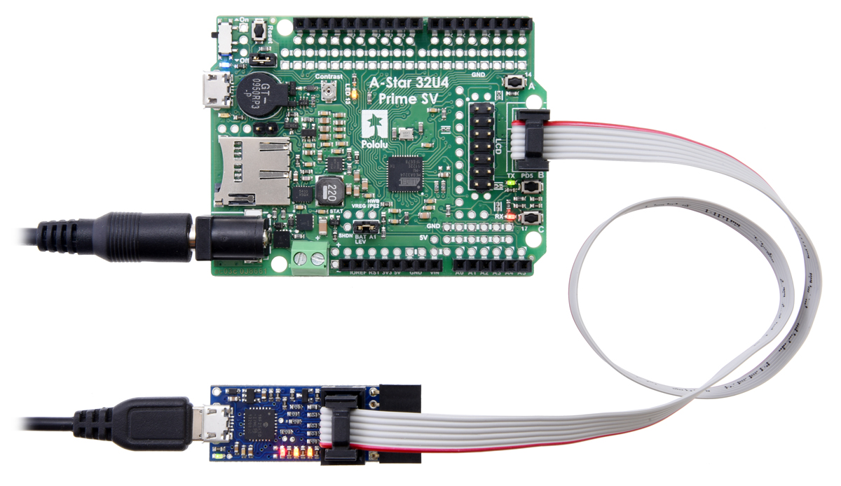 |
The Pololu USB AVR Programmer v2 (bottom) connected to an A-Star 32U4 Prime SV for programming. |
|---|
This section explains how to connect the programmer to an AVR microcontroller using its in-system programming (ISP) interface, which is also known as in-circuit serial programming (ICSP), serial programming, or serial downloading.
Many AVR boards feature a 6-pin male ISP connector. If your board has a connector like that, you can simply connect the programmer to the ISP header using the included 6-pin ISP cable. If your board does not have a shrouded ISP connector to ensure proper orientation of the cable, then you should make sure the cable is oriented so that pin 1 on the cable’s connector lines up with pin 1 on your target device. The ISP cable’s connector has a faint triangle on it that points to pin 1, and the red wire in the cable also indicates pin 1.
If your AVR does not have a 6-pin ISP connector, then you will need to connect each of the six programming pins from the programmer to the corresponding pin on the AVR. The programmer’s ISP pins are labeled on the bottom of the programmer and also in the diagram below. The names we use for the pins on the AVR programmer match the names typically used for the ISP pins in AVR datasheets. For example, the ATmega328P datasheet indicates that MOSI is one of the names of pin PB3, so you would need to connect the MOSI pin on the AVR programmer to the PB3/MOSI pin on the ATmega328P. By referring to your specific AVR’s datasheet and the schematic of the circuit board the AVR is on (if applicable), you should be able to identify connection points for the AVR’s GND, MISO, MOSI, SCK, RST, and VCC pins. You will generally need six wires to make all the required connections.
|
Pololu USB AVR Programmer v2.1, labeled top view. |
|---|
You will also need to make sure that the target device is powered on. The AVR microcontroller must be powered during programming, and the programmer does not supply power by default. If you do want to supply power to the target AVR from the programmer, see Section 8.
5.2. AVR programming using Microchip Studio
If you have an Orangutan or 3pi Robot or wish to use the Pololu AVR C/C++ Library for some other reason, we recommend following the Pololu AVR Programming Quick Start Guide instead of this tutorial.
The following tutorial covers the steps needed to program AVRs in Windows using Microchip Studio (formerly known as Atmel Studio) and a Pololu USB AVR Programmer v2.x. Microchip Studio is a free integrated development environment (IDE) provided by Microchip for Microsoft Windows systems.
You will need to:
- Download and install Microchip Studio by following the instructions on Microchip’s website. This tutorial was written for Microchip Studio 7.0.
- Install the programmer’s drivers on your computer. See Section 4.1 for instructions.
After you have completed these prerequisites, you can create a new Microchip Studio project:
- Open Microchip Studio and click New Project. In the New Project dialog, select GCC C Executable Project for the template. Enter the project name and location. In this tutorial, we will name our project “BlinkLED” and put it in the “C:\” directory, but you can choose a different name and location if you would like. Uncheck the Create directory for solution box to simplify the directory structure of your project. Click OK.
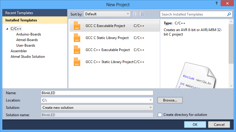 |
The New Project dialog of Atmel Studio 6. |
|---|
- In the Device Selection window, select the device name of your specific AVR. Click OK to create the project.
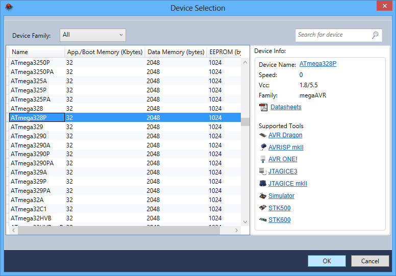 |
The Device Selection dialog of Atmel Studio 6. |
|---|
- Remove the template code that was automatically placed in BlinkLED.c and replace it with the code below:
#define F_CPU 20000000    // AVR clock frequency in Hz, used by util/delay.h
#include <avr/io.h>
#include <util/delay.h>

int main() {
	DDRD |= (1<<1);        // set LED pin PD1 to output
	while (1) {
		PORTD |= (1<<1);   // drive PD1 high
		_delay_ms(100);    // delay 100 ms
		PORTD &= ~(1<<1);  // drive PD1 low
		_delay_ms(900);    // delay 900 ms
	}
}
Note: The value of F_CPU should be the clock frequency of your AVR in units of Hz, so if your AVR is not running at 20 MHz you will need to change that line. If you do not make this change, the timing of _delay_ms() will be off, but the LED will still blink.
- Click the Build Solution button on the toolbar (or press Ctrl+Shift+B) to compile the code.
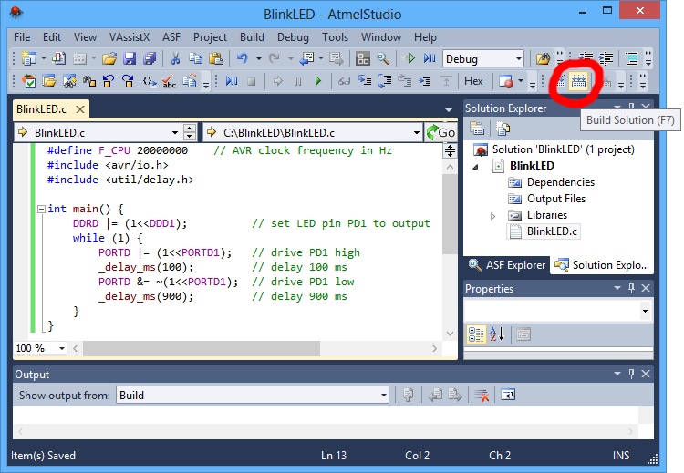 |
Building a project with Atmel Studio 6. |
|---|
- Make sure your programmer is connected to your computer via USB and then select Add target… from the Tools menu. Select STK500 as the tool. Select the COM port that has been assigned to the programmer’s programming port, and click Apply. If you are not sure which COM port to select, run the Pololu USB AVR Programmer v2 Configuration Utility and look in the upper left corner or see Section 4.5, which has more information about determining serial port names. This step can be skipped if you have done it before.
 |
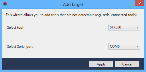 |
The “Add target” dialog box in Atmel Studio 6. |
|---|
- In the Tools menu, select Device Programming.
- This will bring up the Device Programming dialog. For the Tool, select the STK500 that you added earlier. Select the same device you selected earlier. If your device is not available in the list, we recommend upgrading to Microchip Studio 7.0 or later. For the Interface, select ISP. Click Apply.
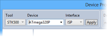 |
Selecting a programmer, device, and interface in the Device Programming dialog of Atmel Studio 6. |
|---|
If you get an error when you click “Apply”, then it means that Microchip Studio is having trouble communicating with the programmer. You should try unplugging the programmer from everything and then plug it back in. You should also make sure you have selected the right COM port. If that does not help, see the Windows USB driver troubleshooting advice in Section 4.1.
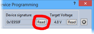
- If you have not done so already, connect the programmer to the target device using the 6-pin ISP cable. Make sure the cable is oriented so that pin 1 on the connector lines up with pin 1 on your target device, and that the target device is powered on. If your device does not have an ISP header, see Section 5.1 for more information about connecting the programmer. You can test the connection by clicking the Read button next to the Device Signature box. This sends a command to the target AVR asking for its signature. If everything works correctly, you should see a number in hex notation appear in the Device Signature box. If you get an error about the signature being wrong, you might have selected the wrong device. If you get a warning that says “Read voltage … is outside selected device’s operating range” then double check to make sure that your device is powered. For more help getting your connection working, see Section 5.6.
 |
Reading the device signature of an AVR in Atmel Studio 6. |
|---|
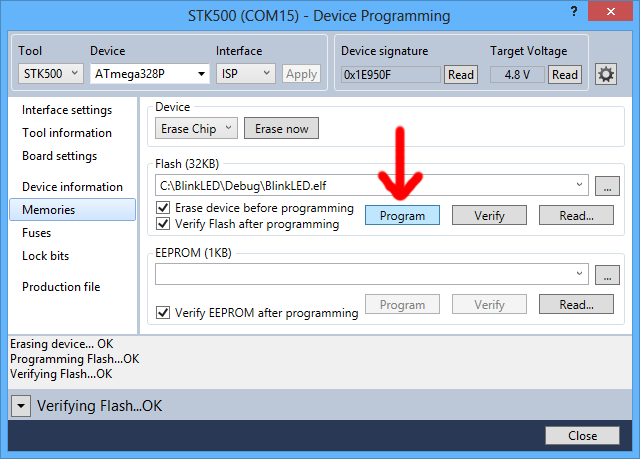
- Now it is time to program your target device. Select the Memories section on the left. The Flash box should contain the path to the ELF file that was generated when you built your program. If it does not, you can browse for this using the “…” button to the right of the text box. If you navigate to your project’s folder, you should find it as “Debug\<project name>.elf”. Click the Program button in the Flash box.
 |
The Memories section of the Device Programming dialog in Atmel Studio 6. |
|---|
As your programmer programs the AVR, you should see all four LEDs flicker and you should see the following text appear at the bottom of the window:
Erasing device... OK
Programming Flash...OK
Verifying Flash...OK
If there were no problems, the LED connected to PD1 of your AVR should now be flashing! Note that if you are trying this on a 3pi robot and you have not yet soldered in the optional through-hole LEDs, the flashing LED will be on the bottom of the robot. If there was a problem, please see Section 5.6 for help identifying and fixing it.
5.2.1. Faster programming with F5 in Microchip Studio
The Device Programming dialog in Microchip Studio is modal, which means you must close it after you are done programming in order to go back to editing your source code. It takes at least 4 clicks to open up the dialog and initiate the programming process again. This section describes a different method for programming that will allow you to compile and program simply by pressing F5.
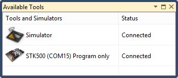
First, in the View menu, select “Available Microchip Tools”. This will bring up the “Available Tools” window. Make sure that there is one and only one STK500 in the list and make sure that the COM port number matches the COM port number of the programmer’s programming port (see Section 4.5). If there are multiple STK500 entries, right click on them and select “Remove” to remove the extra entries. You will only have to do this once.
 |
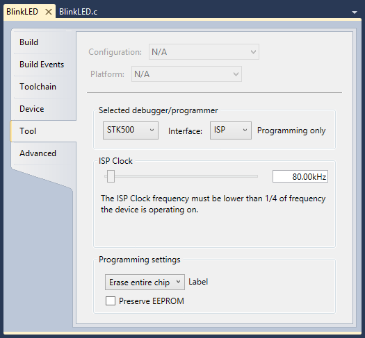
Next, open the project properties window by opening the Project menu and selecting the entry that has the name of your project followed by the word Properties. In the Tool tab, select STK500 as the debugger/programmer, and select ISP as the interface. Set the ISP Clock frequency to 115.2 kHz by dragging the slider; this is a good default value that will work for most AVRs, but you can try increasing it later if you want the programming to be faster.
 |
Finally, you should be able to press F5 to build your project and program the resulting HEX file onto your AVR. Alternatively you can program by selecting either “Continue” or “Start Without Debugging” from the Debug menu.
5.3. AVR programming using AVR Studio 4
We have not tested the Pololu USB AVR Programmer v2.x with AVR Studio 4, which is a predecessor to Microchip Studio and is no longer supported by Microchip. However, we expect the programmer to work with AVR Studio 4. We recommend using the latest version of Microchip Studio, but if you want to use AVR Studio 4 then you can probably follow the instructions in the Programming AVRs Using AVR Studio 4 section of the user’s guide for our older programmer.
5.4. AVR programming using the Arduino IDE
Note: We do not expect this tutorial to be useful for typical Arduino-compatible boards, which usually come with a bootloader that can be used to load sketches. If you want to use the programmer as a USB-to-serial adapter along with the Arduino IDE to load sketches onto a board using its existing bootloader, see Section 6.3.
The following tutorial covers the steps needed to program AVRs in Windows using the Arduino Software (IDE) and a Pololu USB AVR Programmer v2.x. In this tutorial, we will use the programmer to directly load sketches (programs) onto an AVR using its ISP interface. This could be useful if you want to program a bare AVR chip using the Arduino IDE.
- Download and install the Arduino Software.
- Open the Arduino IDE. A new template program will automatically be generated.
- In the Tools menu, find the Programmer menu, and then select Atmel STK500 development board. If you do not see an entry for the STK500, you should update to Arduino 1.6.5 or later.
- In the Ports menu, select the port that corresponds to the programmer’s programming port. If you are not sure which of the listed serial ports is the programming port, see Section 4.5.
- In the Boards menu, select an entry corresponding to the AVR microcontroller or board you want to program. If there are no entries in the Boards menu that exactly match the target you are trying to program, then there might be one that is close enough to work. For example, if you are programming an ATmega328P running at 16 MHz, then the entry for the “Arduino/Genuino Uno” will probably work since it uses the same processor and clock speed. If needed, you can add a new entry to the Boards menu by locating the “hardware/arduino/avr/boards.txt” file inside your Arduino IDE installation and editing it.
- In the Sketch menu, select Upload with Programmer. This is a special version of the upload command that causes the Arduino software to run AVRDUDE using the settings for an STK500 instead of using the board’s usual bootloader. It should load the default template program onto your AVR. If everything worked, the message “Done uploading.” will appear in the status bar.
If an error occurs during the upload step, the first step to debugging it should be to turn on verbose output during uploading. In the Arduino IDE, under the File menu, selected Preferences, then check the upload checkbox on the line that says Show verbose output during, and click OK. Now when you try to upload again, you will see detailed information about how the Arduino IDE is attempting to load your program. One of the most important things to look at is the command used to invoke AVRDUDE: you should make sure that it says “-cstk500”, uses the right COM port, and specifies the right AVR microcontroller using the “-p” option. For more help troubleshooting, see Section 5.6.
5.5. AVR programming using AVRDUDE
If you have an Orangutan or 3pi Robot or wish to use the Pololu AVR C/C++ Library for some other reason, we recommend following the Pololu AVR Programming Quick Start Guide instead of this tutorial.
While it is possible to program AVRs using an integrated development environment like Microchip Studio or the Arduino IDE, you can also set up your own development environment using a collection command-line utilities. This tutorial will explain how to set up such an environment on Windows, Mac OS X, or Linux. For each of these systems, the first thing we need to do is install AVR GCC, GNU Make, and AVRDUDE. In this tutorial, the phrase “AVR GCC” means the full toolchain, including the compiler, binary utilities (binutils), and AVR Libc. The instructions for installing these prerequisites depend on the specific operating system you are using. Once you have those tools, you can write a simple Makefile that supports compiling a program and loading it onto the AVR.
To successfully complete this tutorial, you will need to know how to use cd and ls to navigate the files on your computer. You will also need to know how to use a text editor to create and edit files.
Installing prerequisites in Windows
On a computer running Microsoft Windows, we recommend that you install the Microchip AVR 8-bit Toolchain for Windows, which is a standalone version of AVR GCC for Windows. The installer is just a simple extractor that will extract the toolchain folder to a location you specify. We recommend specifying “C:\” as the location, which means all the tools will be installed in “C:\avr8-gnu-toolchain”. To make it easy to use the toolchain, you should add “C:\avr8-gnu-toolchain\bin\” to the end of your PATH environment variable, making sure to separate it from any other paths using a semicolon. You can edit environment variables like PATH from the Control Panel.
To get GNU Make and AVRDUDE on Windows, we recommend using MSYS2, a distribution of open-source software for Windows. Be sure to follow the instructions on MSYS2’s website to update the packages that come with MSYS2. Then install AVRDUDE and make by running the following command:
pacman -S make mingw-w64-i686-avrdude
Next, launch MSYS2 using the “MinGW-w64 Win32 Shell” shortcut in your start menu (or by running mingw32_shell.bat). There are other ways to start MSYS2, and if you start it the wrong way, then the 32-bit version of AVRDUDE that we installed above will not be on your PATH, and you will get a “command not found” error later when you try to run AVRDUDE.
If you have trouble using the AVR GCC provided by Microchip or the AVRDUDE provided by MSYS2, another option is to use the versions of AVR GCC and AVRDUDE provided by the Arduino IDE. You would have to add the “hardware\tools\avr\bin” folder inside your Arduino installation to your PATH environment variable.
Installing prerequisites on Linux
GNU Make is very commonly used to build software on Linux, so if you are using Linux then you might have it already. You can run “make -v” in a shell to see if you have it. If you do not have make, you should install it using your system’s package manager.
Next, you should install the AVR toolchain and AVRDUDE. On Ubuntu, you can do this by running:
sudo apt-get install gcc-avr avr-libc avrdude
On Arch Linux, you can run:
sudo pacman -S avr-gcc avr-libc avrdude
For other Linux distributions, you should look in your distribution’s list of packages to find the relevant AVR development tools.
Installing prerequisites on macOS
To install the prerequisites on macOS, we recommend first installing Homebrew. Then run the following commands to install AVRDUDE and homebrew-avr:
brew install avrdude
xcode-select --install
brew tap osx-cross/avr
brew install avr-gcc
Checking the prerequisites
After you have installed the prerequisites, you should open your terminal/shell and try running each tool to make sure it is available. Run the following commands:
avr-gcc -v
make -v
avrdude -v
If you installed the prerequisites correctly, each of the commands above should print a version number and some other information about the corresponding tool.
Compiling a program
First, create a file named main.c with the following contents:
#define F_CPU 20000000    // AVR clock frequency in Hz, used by util/delay.h
#include <avr/io.h>
#include <util/delay.h>

int main() {
    DDRD |= (1<<1);        // set LED pin PD1 to output
    while (1) {
        PORTD |= (1<<1);   // drive PD1 high
        _delay_ms(100);    // delay 100 ms
        PORTD &= ~(1<<1);  // drive PD1 low
        _delay_ms(900);    // delay 900 ms
    }
}
The C code above attempts to blink an LED connected to pin PD1 of your AVR. If you do not have an LED connected to PD1, you should edit it to use a different pin. You should also adjust the definition of F_CPU so that it is equal to the clock speed of your AVR in Hz.
Next, create a file named Makefile with the following contents:
MCU=atmega328p
PORT=$(shell pavr2cmd --prog-port)
CFLAGS=-g -Wall -mcall-prologues -mmcu=$(MCU) -Os
LDFLAGS=-Wl,-gc-sections -Wl,-relax
CC=avr-gcc
TARGET=main

all: $(TARGET).hex

clean:
	rm -f *.o *.elf *.hex

%.hex: %.elf
	avr-objcopy -R .eeprom -O ihex $< $@

$(TARGET).elf: $(TARGET).o
	$(CC) $(CFLAGS) $(LDFLAGS) $^ -o $@

program: $(TARGET).hex
	avrdude -c stk500v2 -P "$(PORT)" -p $(MCU) -U flash:w:$<:i
You should edit the MCU variable in the Makefile to match the part name of the AVR you are using. This will be passed as an argument to both GCC and AVRDUDE.
If you did not install the software for the programmer, then you will not have pavr2cmd, and you should manually set the PORT variable in the Makefile to be equal to the name of the programmer’s programming port. See Section 4.5 for more information about determining port names.
You can now run make to build the program.
Note that this is a simple Makefile that does not have real dependency tracking. It knows that if main.c changes, then the other files need to rebuilt, but it does not account for changes in other files you might add, such as header files.
Programming the AVR
You can run make program to build the code and also program it onto your target AVR using AVRDUDE. If this does not work, see Section 5.6 for help troubleshooting.
AVRDUDE’s terminal mode (the -t option) is not compatible with the programmer because the programmer will exit programming mode and release the target AVR from reset if it receives no programming commands for 1500 ms.
5.6. Troubleshooting AVR programming issues
This section helps solve problems you might have using the Pololu USB AVR Programmer v2.x to program AVRs.
If the programmer blinks its red LED and resets when you plug it into to the AVR:
If you are using Pololu USB AVR Programmer v2, and the programmer’s regulator mode is set to Auto or 3.3 V, and you plug it in to a device running at 5 V with a strong pull-up (less than 10kΩ) on its reset line, the programmer could experience a brown-out reset. After all the pins are connected, the programmer will indicate the brown-out by blinking its red LED four times, and then it will resume normal operation. Any programs using the programmer’s COM ports or its native USB interface might need to be restarted. You can avoid this by setting the regulator mode to 5 V, which can be done by running pavr2cmd --regulator-mode 5v or using the Pololu USB AVR Programmer v2 Configuration Utility. The Pololu USB AVR Programmer v2.1 does not have this problem.
You could also experience a brown-out reset when connecting to an AVR if you have enabled the VCC output feature and the capacitance on the target AVR board’s VCC line is too high. For more information, see Section 8.
If a motor on your Baby Orangutan or 3pi Robot runs briefly:
If you plug a Pololu USB AVR Programmer v2 into a Baby Orangutan or 3pi Robot, motor 2 might run as you are plugging it in. After all the pins are connected, the motor will stop running. You can avoid this by adding set_motors(0, 0); to the beginning of your program (e.g. the first line of main or setup) to ensure that the motor PWM pins are driven low. The Pololu USB AVR Programmer v2.1 has improved circuitry for measuring the target’s logic voltage, which limits the duty cycle of this effect to about 0.2%, so the motor won’t move (but it might make a 25 Hz clicking sound).
If the computer fails to connect to the programmer:
- Make sure that your software is configured to connect to the programmer’s programming port, and not some other serial port on your computer. You can find the name of this port by looking in the upper left corner of the Pololu USB AVR Programmer v2 Configuration Utility software, or by following the instructions in Section 4.5.
- If you are using Microchip Studio and programming with the F5 key does not work, then click View > Available Microchip Tools. This will open the “Available Tools” window. Make sure that there is one and only one STK500 in the list and make sure that the COM port number matches the COM port number of the programmer’s programming port. If there are multiple STK500 entries, right click on them and select “Remove” to remove the extra entries.
- If you are in Windows, make sure you have installed the drivers the programmer needs to operate. Section 4.1 describes how to install the drivers in Windows.
- Make sure your programmer is connected to your computer via a USB A to micro-B cable.
- Try closing all programs using the programmer, unplug the programmer from everything, and then plug it back into USB.
- Try using a different USB cable and a different USB port. Make sure your cable is not a charging-only cable.
- Is the programmer’s green USB status LED on? This is the LED next to the USB connector. If this LED is blinking slowly, then your drivers are not properly installed.
- If you are in Windows, can you see your programmer listed in the Device Manager? The Device Manager should show three devices: under “Universal Serial Bus devices” should be “Pololu USB AVR Programmer v2.1” (or v2), and under “Ports (COM & LPT)” should be “Pololu USB AVR Programmer v2.1 Programming Port” and “Pololu USB AVR Programmer v2.1 TTL Serial Port” (or v2) and there should be no error symbols on the icons representing these devices.
- On Windows, your computer will only let one program at a time have a given COM port open. If you are connected to your programmer’s programming port using another program, such as a terminal or a second instance of Microchip Studio, you will not be able to connect to that same COM port with your programming software. Please make sure you do not have any terminal programs connected to your programmer’s programming port. If you have multiple versions of Microchip Studio running, make sure that you have closed the Device Programming dialogs in all of them. When the Device Programming dialog is open and the Apply button at the top is grayed out, that instance of Microchip Studio has an open connection to your programmer’s programming port.
- See Section 4.1 for some tips on USB troubleshooting for Windows.
- See Section 4.2 for some tips on USB troubleshooting for Linux.
- See Section 4.3 for some tips on USB troubleshooting for macOS.
If the programmer has problems connecting to the target AVR:
- A common cause for this problem is an incorrect connection between your programmer and your target device. See Section 5.1 for information on how to properly connect an AVR to the programmer.
- The target AVR must be powered for programming to work. Please make sure that your target device has power and is turned on. You can get a reading of the AVR’s VCC voltage by running
pavr2cmd -sor looking in the Pololu USB AVR Programmer v2 Configuration Utility. If you are using Microchip Studio, you can get a reading of the AVR’s VCC voltage by clicking the “Read” button next to the Target Voltage box in the upper right corner of the Device Programming dialog. - Your programmer’s ISP frequency must be less than a quarter of your target AVR’s clock frequency, but frequencies that are too low can result in timeouts. The default frequency of 114 kHz should work for most AVRs. Try setting the ISP frequency to 114 kHz using the programmer’s configuration utility, or by supplying the
-B 5option to AVRDUDE. You can also set the frequency using the Device Programming dialog in Microchip Studio, in the “Interface settings” section. If you are programming in Microchip Studio with F5, go to the “Tool” section of your project’s properties and set the frequency to 115.2 kHz by dragging the slider. - If the red error LED is on solid after a programming attempt, then run the programmer’s configuration utility or run
pavr2cmd -sto determine the cause of the error. - There may be a problem with the target device. It is possible to kill a device with a static shock, by incorrectly connecting power, or by programming the fuses incorrectly. There could also be a short or cut trace somewhere on your target device. The ideal way to test for this is to try programming a different device with your programmer, or try using a different programmer to program the target device. If this is not an option, try verifying that the target device is still functional and perform some continuity tests to check for shorts or disconnections on the ISP programming lines. Don’t forget to check the 6-pin ISP cable for shorts as well.
- If you are programming by pressing F5 in Microchip Studio, try using the “Device Programming” dialog instead. You can find it in “Tools” menu.
- It is possible that the AVR’s SPIEN fuse has been set to 1, meaning that the ISP interface is disabled. This could potentially happen if you used the AVR’s debugWIRE interface to program it. The debugWIRE interface is a different interface that is not supported by the Pololu USB AVR Programmer v2.x. To fix this problem, you should use the debugWIRE interface to set the SPIEN fuse to 0.
- There could be additional hardware connected to one of your AVR’s programming pins that interferes with its function. For example, the programmer does not work with the Arduino Nano due to the 1 kΩ pull-up resistor on its reset line, which is too strong compared to the 470 Ω series resistor on the signal from the programmer.
If the verification step fails for flash programming:
- Check the lock bits on your AVR to make sure you do not have any type of code protection or memory lock enabled. Since those settings would prevent the programmer from reading from your AVR’s flash, they would cause verification to fail.
If the verification step fails for fuses or lock bits:
- Verification of fuses or lock bits in AVRDUDE can fail because unimplemented fuse bits are read as an arbitrary, constant value that might be different from the value you tried to program into them. Consult the datasheet of your AVR to find out which fuse bits are unimplemented and then change those bits in your AVRDUDE command to match what AVRDUDE is actually reading from the chip. Be very careful whenever you are changing fuses!
Still need help?
If none of the above troubleshooting suggestions solve your problem, please contact us for support.
5.7. Programming faster
If you are developing code for an AVR microcontroller, you might need to program it dozens or hundreds of times before the code is good. This section gives tips on how to program your AVR quickly so that you can be more productive.
If you are programming from Microchip Studio, you should try using the F5 key as described in Section 5.2.1. Then you can just press the F5 key to save, build, and program.
If you are using AVRDUDE or GNU Make from the command line, you should know that most shells allow you to press the up arrow to go back to the last command you ran. So you can press up arrow followed by Enter to very quickly run the last command. You should also learn the shortcut key for saving a file in your text editor (often Ctrl+S), and learn your operating system’s shortcut key for switching Windows (often Alt+Tab). Then you can just press a quick sequence of keystrokes to save, switch to the terminal, program the AVR, and switch back.
Setting the ISP frequency
You should make sure to set the ISP Frequency setting on your programmer to the highest value that the AVR can handle. The ISP Frequency setting has a large effect on how fast the programmer sends commands to the AVR. The rest of this section talks about how to determine a good frequency and configure your programmer to use it.
For most or all AVRs:
- The ISP Frequency should be less than 1/4 of the target clock frequency if the target clock frequency is less than 12 MHz.
- The ISP Frequency should be less than 1/6 of the target clock frequency if the target clock frequency is greater than or equal to 12 MHz.
These rules apply to most or all AVRs with an ISP interface. If you want to, you can check to see if these rules apply to your AVR by looking for information about the minimum low and high periods for the serial clock (SCK) input in the “Serial Downloading” or “Serial Uploading” section of your AVR’s datasheet.
Here are some recommended values for typical setups:
| AVR Clock Frequency |
ISP Frequency | Microchip Studio Setting |
AVRDUDE Option(1) |
|---|---|---|---|
| 20 MHz | 3000 kHz(2) | 1.843 MHz | -B 0.5 |
| 16 MHz | 2400 kHz(2) | 1.843 MHz | -B 0.5 |
| 12 MHz | 1714 kHz(2) | 1.843 MHz | -B 0.5 |
| 8 MHz | 1714 kHz(2) | 1.843 MHz | -B 0.5 |
| 4 MHz | 750 kHz(2) | 1.843 MHz | -B 0.5 |
| 1 MHz | 114 kHz(3) | 115.2 kHz | -B 4 |
| 32.768 kHz | 6.98 kHz(3) | 7.008 kHz | -B 123 |
(1): If the programmer is already configured to use the specified ISP Frequency, you do not need to supply this option to AVRDUDE, but you probably should just in case.
(2): You should select this frequency using the programmer’s configuration software, so that the programmer will use it instead of the 1.843 MHz frequency requested by Microchip Studio and AVRDUDE.
(3): Optional setting: the Microchip Studio and AVRDUDE settings will configure the programmer to use this frequency or a nearby frequency that will also work.
The Pololu USB AVR Programmer v2.x emulates the STK500 programmer from Microchip, which supports 255 different frequencies. Microchip Studio and AVRDUDE only know about those 255 frequencies, and their user interfaces allow you to select one. The fastest frequency the STK500 supports is 1.843 MHz. If you try to select that frequency in AVRDUDE or Microchip Studio, then the programmer will actually use its Max ISP Frequency, a configurable setting which defaults to 1714 kHz.
The ISP Frequency column above lists ISP frequencies supported by the Pololu USB AVR Programmer v2.x which are appropriate for programming an AVR with the specified clock frequency. You can select these ISP frequencies using the --freq option to pavr2cmd or you can select them in the configuration utility. Just click the arrow on the “ISP Frequency” input, select the frequency you want to use, and then click “Apply Settings” to apply the settings to the device.
The Microchip Studio Setting column above shows the frequency you should select in Microchip Studio if you are using Microchip Studio to program. Microchip Studio will always set the ISP frequency of the programmer, whether you are using the F5 key to program, or using the Device Programming dialog. If you are using F5 to program, you should check the “Tool” section of your project’s properties and set the ISP Clock to the value listed above. If you are using the Device Programming dialog, you should set the ISP Clock using the “Interface settings” section of the dialog.
The AVRDUDE Option column above shows the command-line arguments you should supply when running AVRDUDE. The “-B” option to AVRDUDE takes one argument, which is a number. The argument specifies the minimum allowed ISP period (one divided by the maximum allowed ISP Frequency) in units of microseconds.
Any change to the programmer’s frequency—whether it comes from the programmer’s software, or Microchip Studio, or AVRDUDE—is stored in the programmer’s non-volatile memory, so it will persist even if the programmer is unplugged and powered off.
You can change the ISP Frequency and Max ISP Frequency settings using the programmer’s configuration software. The Max ISP Frequency must always be equal to the ISP Frequency if the ISP Frequency is 462 kHz or higher. If you set the ISP Frequency to anything higher than 462 kHz, the programmer’s software automatically sets the Max ISP Frequency setting as well.
The programmer itself runs at 12 MHz, so each possible value for the ISP Frequency and Max ISP Frequency settings is equal to 12000 kHz divided by some whole number.
If you have any issues related to the frequency settings, you can use the configuration software to set them back to their default values of 114 kHz for the ISP Frequency and 1714 kHz for the Max ISP Frequency, respectively. You can also try resetting all of the programmer’s settings to their factory defaults by running pavr2cmd --restore-defaults or selecting “Restore Default Settings” from the “Device” menu of the configuration utility.
5.8. Reading and writing from EEPROM and flash
The Pololu USB AVR Programmer v2.x supports reading and writing from an AVR’s EEPROM and flash memories.
If you are using Atmel Studio, you can use the “Memories” section of the “Device Programming” dialog to read and write from EEPROM and flash.
If you are using AVRDUDE, you can use the “-U” option:
- To read from flash and save the contents to a HEX file, use something like
-U flash:r:filename.hex:i - To write a HEX file to flash, use something like
-U flash:w:filename.hex:i(and see Section 5.5) - To read from EEPROM and save the contents to a HEX file, use something like
-U eeprom:r:filename.hex:i - To write a HEX file to EEPROM, use something like
-U eeprom:w:filename.hex:i
In the examples above, filename.hex should be changed to actual name of the file you want to use.
Don’t forget to pass the other required options to AVRDUDE. A complete AVRDUDE command to read from EEPROM would look something like this:
avrdude -c stk500v2 -P COM6 -p atmega328p -U eeprom:r:filename.hex:i
You’ll need to change “COM6” to the actual name of the programmer’s programming port, which you can find by running pavr2cmd --prog-port or by following the instructions in Section 4.5.
More information is available in the AVRDUDE manual, which you can see by running man avrdude.
Note: Many AVRs have lock bits which might prevent you from reading the EEPROM or flash without first performing a full chip erase.
5.9. Setting fuses and lock bits
Warning: Modifying an AVR’s fuses can leave it an unusable state. In particular, if you select an invalid clock setting, then the AVR’s clock will not work and you won’t be able to program it. You should make sure you know what you are doing and be very careful when setting the fuses!
The Pololu USB AVR Programmer v2.x supports reading and writing an AVR’s fuses and lock bits.
If you have Windows, the safest and easiest way to set the fuse bits is to use Microchip Studio’s graphical user interface for it, which can be found in the “Fuses” and “Lock bits” section of the “Device Programming” dialog. In case “Auto read” is turned off, click the “Read” button to read your device’s settings. Then make any changes you want to make and click “Program”.
The fuses and lock bits can also be set using AVRDUDE. Here is an example command:
avrdude -c stk500v2 -P COM6 -p m32u4 -U lock:w:0xHH:m \
  -U efuse:w:0xHH:m -U hfuse:w:0xHH:m -U lfuse:w:0xHH:m
To make the command above work, you would need to replace each H with a hexadecimal digit. Refer to the your AVR’s datasheet to figure out the right values for each configuration byte.
You’ll also need to change “COM6” to the actual name of the programmer’s programming port, which you can find by running pavr2cmd --prog-port or by following the instructions in Section 4.5.
5.10. Using the clock output to revive AVRs
It is possible to disable an AVR if you accidentally set its clock-related fuses to something invalid. The clock settings must be valid for any kind of programming to work. If you are having trouble programming an AVR and think it might be due to invalid clock settings, you can try the steps below to supply a 100 kHz clock signal to the AVR and revive it.
- Connect the AVR to the programmer in the usual way as described in Section 5.1.
- Configure the programmer’s B pin to be a 100 kHz clock output by running
pavr2cmd --line-b clockor by opening the Pololu USB AVR Programmer v2 Configuration Utility, changing “Line B function” to “Clock (output)”, and clicking “Apply Settings”. - Set the programmer’s ISP Frequency to 1.465 kHz by running
pavr2cmd --freq 1.465or by using the configuration utility. - Connect a wire from the programmer’s B pin to the AVR’s XTAL2 pin.
- Perform a full chip erase. In Microchip Studio, you can use the “Erase now” button in the “Memories” section of the “Device Programming” dialog. If you are using AVRDUDE, you can take a command you would normally use for programming, and replace the “-U” option and its arguments with “-e”.
- If the chip erase did not work, connect the B pin to XTAL1 and try again.
- If you still cannot get the chip erase to work, read the troubleshooting advice in Section 5.6. If you change anything, be sure to try both XTAL1 and XTAL2 again.
- If you still cannot get the chip erase to work, then there is probably something wrong with the AVR besides its clock settings, and you will not be able to revive it using these steps.
- Reprogram your chip’s fuses to appropriate values. The easiest way to do this is to use Microchip Studio’s user interface, but you can also use AVRDUDE as described in Section 5.9.
- Disconnect the clock signal from the programmer, and set the programmer’s ISP frequency back to a reasonable value like 114 kHz.
- Try programming to ensure that everything is working as expected. If this works, then you have successfully revived the AVR!
6. USB-to-TTL serial adapter
6.1. Asynchronous serial communication
One bonus feature of the Pololu USB AVR Programmer v2.x is the USB-to-TTL-serial adapter, which can be used for connecting microcontroller projects to a personal computer. The USB-to-TTL-serial adapter looks like a standard serial port to the operating system, allowing you to use existing terminal programs and software designed to use serial ports. This feature is similar to our CP2104 USB-to-Serial Adapter Carrier.
The TX and RX lines of the programmer are used to perform asynchronous serial communication. When the programmer receives a byte from the computer via USB, it will transmit that byte on the TX line. When the programmer receives a byte on the RX input line, it will send that byte back to the computer via USB.
The bytes are sent and received eight bits at a time, with the least significant bit first, with no parity and one stop bit. This coding is sometimes abbreviated 8N1. The bits must be non-inverted, meaning that a zero is sent as low voltage, and a one is sent as high voltage. All devices involved in asynchronous serial communication need to agree ahead of time on the duration of one bit (the baud rate), so all devices must be independently configured to run at the same baud rate before they will be able to communicate with each other. The programmer supports all integer baud rates from 300 to 115200 bits per second. The following figure is an example of an 8N1 TTL serial byte transmitted at 5 V:
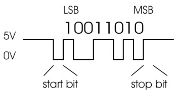 |
To make a working serial connection between the programmer and another device, you should make sure to run the programmer at a voltage that is equal to or close to the voltage of the other device. The programmer’s voltage regulator controls what voltage it will be using, and the regulator settings are described in Section 7.
To use the USB-to-TTL-serial adapter, you must determine what port name the operating system has assigned it. You can look in the upper left corner of the Pololu USB AVR Programmer v2 Configuration Utility, or you can run pavr2cmd --ttl-port, or you can follow the instructions in Section 4.5.
After determining the port name, you can use any serial port software to communicate on that port. There are many free terminal programs available, including PuTTY (Windows or Linux), Tera Term (Windows), Br@y Terminal (Windows), and screen (Linux or Mac OS X). Advanced users developing scripted applications might prefer the free terminal program kermit. To use any of these terminal programs with the USB-to-TTL-serial adapter, you must specify the port name determined above and your desired baud rate. The characters you type will be transmitted on the programmer’s TX line. Bytes received by the programmer on the RX line will be displayed on the screen by the terminal program.
If you need to send and receive non-ASCII bytes, you can use the Pololu Serial Transmitter Utility for Windows.
You can also write your own computer program to use the serial port. Windows, Linux, and Mac OS X all provide C APIs for serial port communication. The Microsoft .NET framework supports serial port communication with the System.IO.Ports.SerialPort class. The Qt framework provides the QSerialPort class. Java programs can use the RXTX library.
6.2. Serial control lines
In addition to transmitting bytes on the TX line and receiving bytes on the RX line, the USB-to-TTL-serial adapter can use programmer pins A and B as serial handshaking lines of your choosing. Each pin can be configured as an input or an output by identifying it with a serial handshaking line. By default, A is an unused pin that is pulled high, and B is DTR. To change the functions of A and B, you can use the --line-a and --line-b options of pavr2cmd or you can configure the lines in the Pololu USB AVR Programmer v2 Configuration Utility.
The following options are available for those lines:
- (none): The pin will not be used as a serial handshaking line. It will be an input that is pulled high.
- CD (input): The pin will be an input that is pulled high, and the input’s value will be relayed to the computer as the CD signal.
- DSR (input): The pin will be an input that is pulled high, and the input’s value will be relayed to the computer as the DSR signal.
- DTR (output): The pin will be an output that reflects the value of the DTR signal from the computer.
- RTS (output): The pin will be an output that reflects the value of the RTS signal from the computer.
- Clock (output): The pin will be an output that sends a 100 kHz clock signal. This option is only available for pin B.
- DTR reset (output): The pin will normally be floating, but it will drive low for about 1 ms whenever the computer changes the DTR signal from 0 to 1.
(CTS is not available.)
The serial handshaking lines are inverted: unless otherwise specified, a voltage of 0 V corresponds to a logical 1, while a voltage of high voltage (VDD) corresponds to a logical 0.
You can read input lines and/or set output lines by either using a terminal program that supports control signals (such as Br@y Terminal) or by writing a computer program. The Microsoft .NET framework contains a System.IO.Ports.SerialPort class that makes it easy to read and write bytes from a serial port as well as set and read the control signals.
6.3. Connecting to a serial bootloader
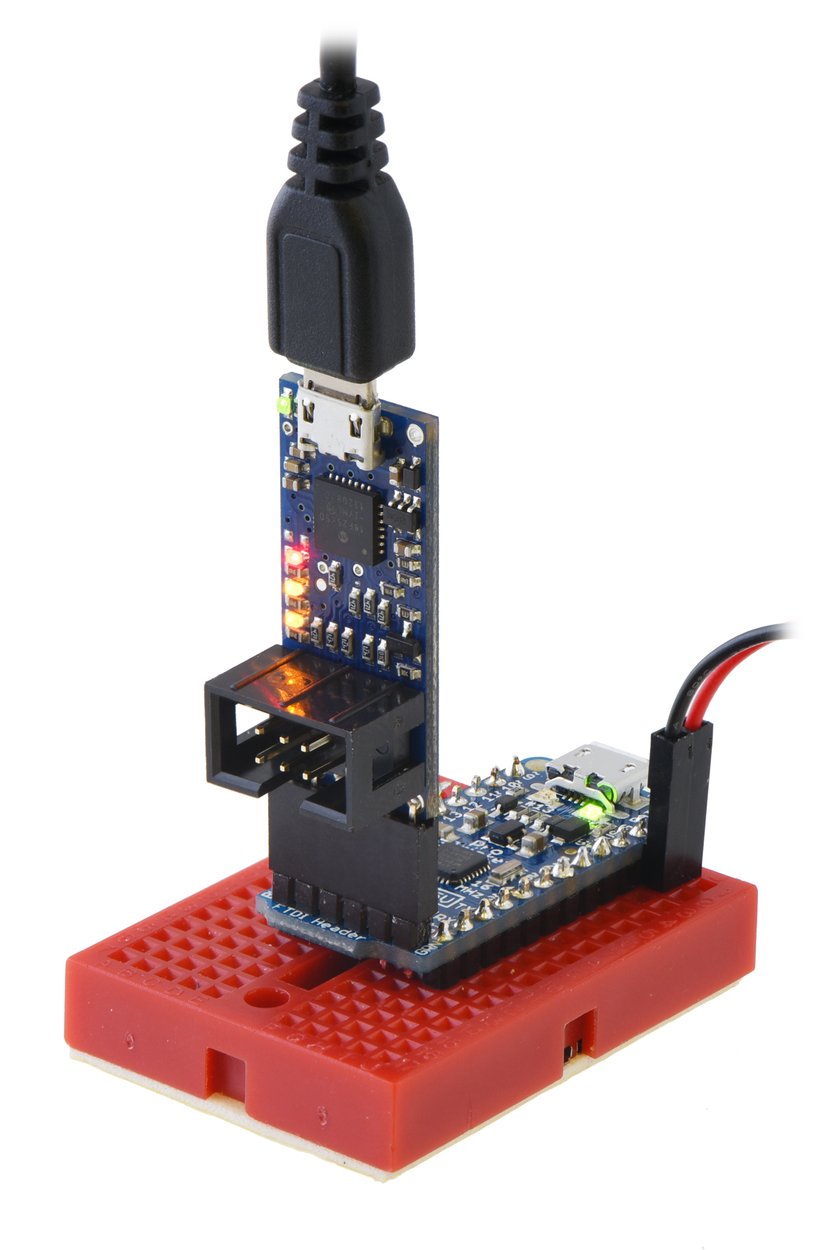 |
The Pololu USB AVR Programmer v2 (top) connected to an Adafruit Pro Trinket for programming. |
|---|
The six pins on the serial header (GND, A, VCC, TX, RX, and B) are arranged to be similar to the pinout of commonly-available FTDI USB-to-serial cables and breakout boards. In the default configuration, pin B is used as the DTR output (and pin A is an unused input). By default, the programmer’s regulator mode is Auto, which means the programmer will operate at 3.3 V when it starts up, but it will change to 5 V if you plug it into a 5 V device.
In this default configuration, the programmer can often be used in place of an FTDI cable: you can plug it directly into various Arduino-compatible boards and use it to upload sketches via a serial bootloader. The rest of this section explains the details of how this works.
When you click the “Upload” button in the Arduino IDE to program an Arduino such as the Arduino Uno, the IDE will run AVRDUDE with a command like this:
avrdude -patmega328p -carduino -PCOM6 -b115200 -D -Uflash:w:Sketch.ino.hex:i
The -carduino option specifies that AVRDUDE is going to talk to an Arduino-style serial bootloader. This means that after AVRDUDE opens up the specified serial port (COM6 in this case), it will set the DTR and RTS signals on that port to 0, and then set them to 1. Typical serial terminal programs will also set DTR and RTS to 1. When the signals change from 0 to 1, the programmer’s DTR line will change from a high voltage (VDD) to low (GND). The board with the AVR on it will usually have a simple circuit with a capacitor so that when DTR changes from high to low, the reset line of the board’s AVR sees a low pulse, making it reset.. This feature is called “auto-reset”. Resetting the AVR like this causes its bootloader to run, and AVRDUDE will attempt to talk to the bootloader using the programmer’s RX and TX lines in order to upload the specified HEX file.
Using the programmer’s configuration software, you can change pin A or B to be the DTR reset signal. This is an output that is designed specifically for the auto-reset feature. Whenever DTR changes from 0 to 1, the programmer will drive DTR reset low for 1 ms. You can plug the DTR reset signal directly into an AVR microcontroller’s RST line without needing to use a capacitor.
7. Power settings and status
The Pololu USB AVR Programmer v2.x has several settings that affect how power is regulated, distributed, and monitored. These settings can be seen and changed in the Pololu USB AVR Programmer v2 Configuration Utility or from the command-line utility pavr2cmd. These settings are stored in the programmer’s non-volatile memory, so they will persist while the programmer is unpowered.
The Regulator mode setting determines what voltage the programmer will operate at, and it has three options:
- Auto (default): In this mode, the programmer will operate at 3.3 V when it starts up, and it will switch to 5 V if the voltage on VCC rises above 4096 mV. The programmer will switch back to 3.3 V if the voltage on VCC falls below 3712 mV.
- 5 V: The programmer will operate at 5 V during normal operation. It will still be running at 3.3 V briefly when power is first applied, and it will still run at 3.3 V when it is in bootloader mode (which is used for firmware updates).
- 3.3 V: The programmer will always operate at 3.3 V.
The VCC output setting determines whether the VCC pin (which is on both the ISP connector and the serial header) will be an input or an output. By default, the VCC output is disabled, so the VCC pin will be an input. If you set the VCC pin to be an output, you must also set the regulator mode to either 5 V or 3.3 V: that setting specifies both the voltage that the programmer will operate at and the voltage that it will supply to the VCC pin. Using the VCC pin as an output can be useful for powering low-current systems from USB. See Section 8 for more details.
If VCC is configured to be an output, then one or both of the yellow LEDs will blink eight times per second to warn you, as described in Section 4.4. If you do not want the LEDs to be blink so fast, you can change the VCC Output Indicator setting from “Blinking” (the default) to “Steady” using the configuration software. This makes the yellow LEDs just stay on solid instead of blinking eight times per second.
There are several settings that define what voltage levels on the programmer’s VDD line and the target AVR’s VCC line are acceptable. Each of these settings can only be set to a value that is a multiple of 32 mV.
The VCC/VDD maximum range setting, which is 896 mV by default, defines the maximum allowed difference between the highest measurement and the lowest measurement for both the programmer’s VDD line and the target AVR’s VCC line. If the VCC or VDD varies by more than this amount during programming, then the programmer will abort the current programming session.
The VCC 3.3 V minimum and VCC 3.3 V maximum settings, which are 2720 mV and 3872 mV by default, define the acceptable voltages for the target’s VCC line when the programmer’s regulator is set to 3.3 V. If the VCC measurement ever returns a value outside of this range, the programmer will abort the current programming session.
Similarly, the VCC 5 V minimum and VCC 5 V maximum settings, which are 4128 mV and 5856 mV by default, define the acceptable voltages for the target’s VCC line when the programmer’s regulator is set to 5 V.
The programmer also measures its own VDD voltage during programming. If the regulator is set to 3.3 V, the programmer expects the VDD measurements it to be no less than 2912 mV. It also expects the VDD measurements to either be no more than 3712 mV, or to be no more than 256 mV higher than the target’s VCC power. If the regulator is set to 5 V, the programmer expects the VDD measurements to be between 3584 mV and 5792 mV.
Power status information
You can see a lot of information about the programmer’s power status in the Pololu USB AVR Programmer v2 Configuration Utility and the command-line utility pavr2cmd. If you are using the configuration utility, these variables are updated each second while the utility is connected to the programmer. In the “Current status” box, you can see the latest measurements of the programmer’s VDD voltage and the target’s VCC voltage. You can also see the VDD regulator set point, which is the voltage that the programmer is currently setting the regulator to (3.3 V or 5 V).
After any programming attempt, the minimum and maximum measurements for both the programmer’s VDD and the target’s VCC are shown in the “Results from last programming” box.
8. Using VCC or VBUS to supply power
Generally, when you are programming an AVR or using the programmer’s USB-to-TTL serial header, the device you are interfacing with should be powered from its own power supply. The programmer does not supply any power on its VCC pins by default. However, if you want to power a low-current and low-capacitance load, you can configure VCC to be an output using the progammer’s configuration software. When VCC is an output, its voltage will either be 3.3 V or 5 V, and that is determined by the programmer’s “Regulator mode” setting.
If your target board has too much capacitance on VCC, then it could cause the programmer to brown-out or it could cause disruptions in the USB communication. The Pololu USB AVR Programmer v2 cannot handle more than a few µF of capacitance on VCC. The Pololu USB AVR Programmer v2.1 has an improved power switch with a controlled slew rate, so it can power target boards with up to about 33 µF on VCC. The Pololu USB AVR Programmer v2.1 still might experience a brown-out reset when you connect it to a target with more than a few µF of capacitance, but after browning out once it is often able to recover and supply power to the target.
You should not connect VCC to the output of any other device, since that could cause a short circuit. You should not draw more than 80 mA of current from VCC.
Alternatively, you can use the programmer’s VBUS pin to power external devices. This pin is connected directly to the power line of the USB cable. As with the VCC output, you should not draw more than 80 mA, and you should not have too much capacitance.
It is generally safer to use the VCC output than to use VBUS. The power supplied to the VCC output goes through a diode, which prevents current from flowing back into the USB port, and the programmer’s linear regulator, which has current limiting. The VBUS pin provides no protections, so there is a higher risk that you would accidentally damage something.
9. Upgrading firmware
The firmware of the Pololu USB AVR Programmer v2.x is the program that runs inside the programmer itself. The programmer has field-upgradeable firmware that can be updated when bug fixes or new features are available.
Most users should not need to upgrade the firmware. We only recommend upgrading the firmware if you know that your programmer has an old version of the firmware and that a newer version of the firmware has a specific change that you want.
Firmware versions
- Version 1.00: This is the original version.
- Version 1.01, released on 2016 Jun 20: This version makes the measurements of the voltage on VDD and VCC more accurate.
- Version 1.02, released on 2018 Mar 23: This version adds support the new Pololu USB AVR Programmer v2.1. This version contains no important changes for the Pololu USB AVR Programmer v2, so we do not provide a download for it.
Checking your firmware version
To determine which firmware version you are currently using, connect your programmer to your computer via USB and run the Pololu USB AVR Programmer v2 Configuration Utility. The firmware version is displayed in upper left corner. Alternatively, you can run pavr2cmd -s.
Upgrade instructions
To upgrade the firmware, follow these steps:
- If you have not done so already, you will need to install the Pololu USB Bootloader Utility, a command-line utility that supports firmware upgrades for several Pololu products. This program is also known as “p-load” because that is the command used to run it from a command prompt. Use the links below to download and install p-load:
- Windows: Download and install the Pololu USB Bootloader Utility (p-load) for Windows (1MB msi).
- Mac OS X: Download and install the Pololu USB Bootloader Utility (p-load) for Mac OS X (87k pkg).
- Linux: Download the Pololu USB Bootloader Utility (p-load) for Linux (x86) (478k xz) (which works on 32-bit and 64-bit systems) or the Pololu USB Bootloader Utility (p-load) for Linux (Raspberry Pi) (478k xz).
- Download the latest version of the firmware here:
- If you changed any of the programmer’s settings in the configuration utility or with
pavr2cmd, record your current settings because the firmware upgrade process will reset the settings. - Close the Pololu USB AVR Programmer v2 Configuration Utility and any other programs that might be using the programmer.
- Open a command prompt and run the following command, replacing filename with the full path to the firmware file that you downloaded:
p-load -w "filename"
For example, if you are using Windows, and your username is Casey, and you saved the firmware to your Downloads folder, then you could run:p-load -w "C:\Users\Casey\Downloads\pgm04a-v1.01.fmi"
- When you run the command above, the Pololu USB Bootloader Utility should take care of everything needed to upgrade the programmer’s firmware.
If you run into problems during a firmware upgrade, please contact us for assistance.
Related products


Home | Forum | Blog | Support | Ordering Information | Lists | Distributors | BIG Order Form | About | Contact
© 2001–2026 Pololu Corporation
