Support »
Application Note: MLX90614ESF SMBus Communication with Orangutan Robot Controllers

View document on multiple pages.
You can also view this document as a printable PDF.
1. Overview
The MLX90614ESF temperature sensor is a high-accuracy, high-resolution, non-contact thermometer with a 90-degree field of view. It has a measurement resolution of 0.02°C and is factory calibrated for a wide -70 to 380°C object temperature range. The sensor uses an SMBus (I²C-compatible) digital interface and can be configured to output a customizable 10-bit PWM output for continuous readings. In this guide, we show how to connect the MLX90614ESF to an Orangutan robot controller and read the temperature using the SMBus interface.
2. Construction
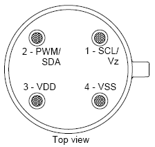
The following diagram, taken from page 6 of the MLX90614ESF datasheet (749k pdf), shows the MLX90614ESF pinout as seen when looking at the top of the sensor.
 |
- VSS: Ground. The metal can is also connected to this pin.
- SCL / Vz: Serial clock input for 2 wire communications protocol. 5.7V zener is available at this pin for connection of external bipolar transistor to MLX90614A to supply the device from external 8 -16V source.
- SDA / PWM: Digital input / output. In PWM mode, the measured object temperature is available at this pin Pulse Width Modulated. In SMBus-compatible mode, this pin is automatically configured as open drain NMOS. The sensor ships in SMBus-compatible mode.
- VDD: External supply voltage (4.5 – 5.5 V).
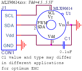
Connect the sensor to the Orangutan as shown below to enable SMBus communication. If you are using an Orangutan based on the ATmega328, ATmega168, or ATmega48, connect its PC4 pin to SDA (sensor pin 2) and PC5 pin to SCL (sensor pin 1); if you are using the Orangutan X2, which is based on the ATmega644, connect its PC1 pin to SDA and PC0 pin to SCL. VSS (sensor pin 4) connects to the Orangutan’s ground rail, and VDD (sensor pin 3) connects to the Orangutan’s regulated 5V power bus. It is recommended that you solder a 0.1 uF capacitor between power (VDD) and ground (VSS).
|
|
3. Software
This sample program reads the temperature from the MLX90614ESF’s RAM using SMBus. The program works with our Orangutan robot controllers (except for the Orangutan X2) and uses the Pololu AVR C/C++ Library to print the measured temperature to the LCD. For specific information on how to program your Orangutan, read its User’s Guide, which can be found on the resources tab of the product’s website.
#include <avr/io.h>
#include <pololu/orangutan.h>

void i2c_start() {
	TWCR = (1 << TWINT) | (1 << TWSTA) | (1 << TWEN);	// send start condition
	while (!(TWCR & (1 << TWINT)));
}

void i2c_write_byte(char byte) {
	TWDR = byte;
	TWCR = (1 << TWINT) | (1 << TWEN); // start address transmission
	while (!(TWCR & (1 << TWINT)));
}

char i2c_read_byte() {
	TWCR = (1 << TWINT) | (1 << TWEA) | (1 << TWEN);	// start data reception, transmit ACK
	while (!(TWCR & (1 << TWINT)));
	return TWDR;
}

void i2c_receive_pec() {
	TWCR = (1 << TWINT) | (1 << TWEN);	// start PEC reception, transmit NACK
	while (!(TWCR & (1 << TWINT)));
}

void i2c_stop() {
	TWCR = (1 << TWINT) | (1 << TWSTO) | (1 << TWEN); // send stop condition
}

//Returns 100 times the temperature read by the sensor giving a 0.01 degree resolution.
long i2c_read_temperature_f() {
	long low_byte, high_byte;

	DDRC = 0;							// all inputs
	PORTC = (1 << PORTC4) | (1 << PORTC5);	// enable pull-ups on SDA and SCL, respectively

	TWSR = 0;		// clear bit-rate prescale bits
	TWBR = 192;		// produces an SCL frequency of 50 kHz with a 20 MHz CPU clock speed.

	i2c_start();
	// The expected value of TWSR & 0xF8 is now 0x08 (Start condition transmitted).

	i2c_write_byte(0);// 0 is the universal write address for slaves.
	// The expected value of TWSR & 0xF8 is now 0x18 (SLA+W transmitted ACK received).

	i2c_write_byte(0x07); // read TObj1 (0x07) from RAM
	// The expected value of TWSR & 0xF8 is now 0x28 (Data transmitted ACK received).

	i2c_start();
	// The expected value of TWSR & 0xF8 is now 0x10 (Repeated start has been transmitted).

	i2c_write_byte(1); // 1 is the universal read address for slaves.
	// The expected value of TWSR & 0xF8 is now 0x40 (SLA+R transmitted ACK received).

	low_byte = i2c_read_byte();
	// The expected value of TWSR & 0xF8 is now 0x50 (Data received ACK received).

	high_byte = i2c_read_byte();
	// The expected value of TWSR & 0xF8 is now 0x50 (Data received ACK received).

	i2c_receive_pec();  // read packet error code (PEC)
	// The expected value of TWSR & 0xF8 is now 0x58 (Data received NOT ACK received).

	i2c_stop();

	// Tk is temperature in Kelvin, Tf is temperature in degrees Fahrenheit, To is the raw
	// value of the object temperature as returned by the sensor
	// 100 Tk = To × 2 (from the datasheet section 8.7.2--To has the units 0.02K)
	// Tf = Tk × 9/5 - 459.67 (conversion from Kelvin to Farenheit)

	// 100 × Tf = 100 × Tk ×  9/5 - 45967
	// 100 × Tf = To  × 2  × 9/5  - 45967
	// 100 × Tf = To  × 18/5      - 45967
	return (256*high_byte+low_byte) * 18/5 - 45967;  // return temperature in units of 0.01°F
}


int main()
{
	long object_temperature_f;
	clear();
	print("press");
	lcd_goto_xy(0, 1);
	print("button");

	wait_for_button(ALL_BUTTONS);
	clear();
	while (1)   // loop forever
	{
		object_temperature_f = i2c_read_temperature_f();

		lcd_goto_xy(0, 0);
		// print the temperature in degrees Fahrenheit on the LCD (this code formats it nicely)
		if (object_temperature_f < 0)
		{
			print("-");
			object_temperature_f = -object_temperature_f;
		}
		long integer_temperature = object_temperature_f / 100;
		print_long(integer_temperature);
		print(".");
		long decimal = object_temperature_f - integer_temperature * 100;
		if (decimal < 10)
			print("0");
		print_long(decimal);
		print_character(223);		// degree symbol
		print("F   ");
		delay_ms(75);
	}

	return 0;
}


