Support »
Basic LEGO Robot

View document on multiple pages.
You can also view this document as a printable PDF.
- 1. Introduction
- 2. Materials and Tools
- 3. Hardware Construction
- 4. BASIC Stamp II Software
- 5. Results and Conclusion
1. Introduction
 |
The BASIC Stamp from Parallax is a popular introductory miniature computer for learning the basics of electronics and computer programming. By themsleves, however, the BASIC Stamps cannot control motors, which are crucial to robotics and many other projects that require motion. LEGO is famous for its construction blocks, and it has lately been introducing many robot-themed sets. In this project, we demonstrate how you can use the Pololu micro dual serial motor controller to control a simple LEGO robot with a BASIC Stamp.
In its initial configuration, this robot behaves very similarly to the obstacle-avoiding robot from project 1: this robot drives forward until it hits an obstacle; when it does, it backs up, turns, and resumes its forward motion. In future projects, we will use this project as a foundation for more complex and interesting robots.
Because the details of the mechanical design are not particularly interesting, we will not cover the assembly of the LEGO chassis. Instead, we will focus on how to use the micro motor controller with the BASIC Stamp II. This sample project should, therefore, serve as a reference for anyone wanting to use a BASIC Stamp to control a small, differential-drive robot (a type of robot, which, like a bulldozer or tank, has independent drive wheels or treads on its two sides).
2. Materials and Tools
Here are the essential parts you will need if you want to build a similar robot. Except for the LEGO chassis, these items are available either from Pololu or from most electronic component distributors.
- Pololu micro dual serial motor controller
- BASIC Stamp II from Parallax
- Small, differential-drive chassis
- Two long-lever, snap-action switches for use as bumper switches
- Small solderless breadboard
- Two 10k resistors for use as pull-ups for the bumper switches
- 9V battery and battery snap
- Hook-up wire
- Power switch
You might also need these basic tools to prepare you chassis:
- Diagonal cutters
- Wire strippers
- Soldering iron and solder
- Hot glue gun
3. Hardware Construction
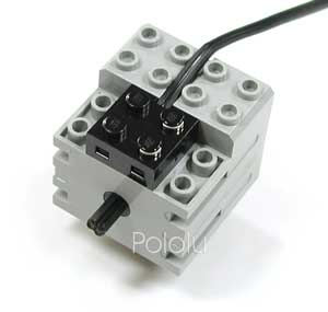 |
Although we do not wish to dwell on the mechanical aspects of this project, the LEGO motor is worth mentioning. Within the compact housing are both a small motor and a very efficient gearbox. The motor is fairly expensive, but you’ll immediately appreciate how much more quietly it runs than cheaper gearboxes. Because the motor draws only approximatly 100 mA, it is perfect for use with our micro motor controller.
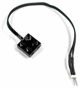 |
To use the LEGO motors in you own project, you need to get leads that you can connect to your own electronics. One possibility is to cut a regular LEGO cable in half and solder on male header pins onto the cut wires. This will give you the two necessary connectors at the expense of one LEGO cable.
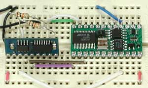 |
We built the electronics on a small solderless breadboard. As you can see from the close-up picture to the right, there isn’t much to the circuit. The only components other than the BASIC Stamp II and the motor controller are the two pull-up resistors for the bumper switches. The schematic diagram for this circuit is shown below.
 |
Using the BASIC Stamp II is very convenient because all of its I/O lines are interchangeable; the only reason we used the particular pins indicated in the schematic is because it made the wiring convenient. The Stamp’s on-board voltage regulator allows it to run straight off of a 9-volt battery, and the LEGO motors are designed to run at 9V as well. The Stamp’s regulated 5V output is used for the motor controller’s logic power supply. The diagram does not show the Stamp’s 12 I/O lines available for expansion.
4. BASIC Stamp II Software
(In this section, we go over the major features of the program. For more details, view the entire program (3k bs2). Note that the pin numbers used in the program correspond to the schematic diagram in section 3, above.)
The BASIC Stamp makes serial I/O very straightforward with its serout
instruction. A typical use of the instruction is:
serout MC_SOUT, 32, [$80, 0, LFWD, SPEED] 'Left motor forward at SPEED
The first value,
MC_SOUT, specifies the serial output pin to use, which is P10 in our example.
The second argument, 32, specifies the settings for the serial output; we use
32 because it specifies the baud rate to be 19,200, which is the maximum rate at
which the motor controller can receive. The four values in square brackets
are the values sent out over the serial line.
The first two values sent to the motor controller are always hex 80 (128 in decimal) and 0, which let the motor controller know that it is being issued a command. The third value specifies the motor number and direction. To help prevent mistakes with this third parameter, we defined constants for forward and backward for our two motors at the beginning of our program:
  LFWD		con	0
  LBAK		con	1
  RFWD		con	2
  RBAK		con	3
(Of course, which constant gets assigned which number depends on how your robot is wired up and what you call forward and reverse or left and right.) The final parameter in the 4-byte sequence is the speed at which the motor should run, where 0 stops the motor and 127 (7F hex) is full speed.
Note:
At the beginning of the program, it is important to reset the motor
controller. Make sure the serial line is high
before you reset the motor controller:
high MC_SOUT ’serial line idle state low MC_RESET ’reset motor controller high MC_RESET |
The main loop of the program is rather simple since the robot
does not do much. For simplicity, we use the pause
instruction to determine the time that the robot backs up or turns,
but the BASIC Stamp could potentially be doing something more useful
during that time.
loop:	'Go forward till bump something
	serout MC_SOUT, 32, [$80, 0, LFWD, SPEED]	'Left and right motors forward at SPEED
	serout MC_SOUT, 32, [$80, 0, RFWD, SPEED]	'32 indicates 8 bits, no parity, non-inverted,
								' buad rate 19200
	if (RBUMP = 0) then rbumped			'If bumped, turn backward in appropo direction
	if (LBUMP = 0) then lbumped
	goto	loop


rbumped: 'Turn backward right, then spin left in place for a random time
	serout MC_SOUT, 32, [$80, 0, LBAK, SPEED]		'Turn backward for 1 sec
	serout MC_SOUT, 32, [$80, 0, RBAK, SLOWSPEED]
	pause 1000

	serout MC_SOUT, 32, [$80, 0, LBAK, SPEED]	'Spin in place for random time, TURNTIME
	serout MC_SOUT, 32, [$80, 0, RFWD, SPEED]
	random TURNTIME
	pause (TURNTIME*5) + 250			'pause between 0.25 and 1.5 seconds

	goto loop


lbumped: 'Turn backward left, then spin right in place for a random time
	serout MC_SOUT, 32, [$80, 0, LBAK, SLOWSPEED]
	serout MC_SOUT, 32, [$80, 0, RBAK, SPEED]
	pause 1000

	serout MC_SOUT, 32, [$80, 0, LFWD, SPEED]
	serout MC_SOUT, 32, [$80, 0, RBAK, SPEED]
	random TURNTIME
	pause (TURNTIME*5) + 250

	goto loop
For more details, view the entire program (3k bs2). Note that the pin numbers used in the program correspond to the schematic diagram above.
5. Results and Conclusion
This project shows how easy it is to use the Pololu micro motor controller with a BASIC Stamp II. While the robot we built is certainly very simple, it is still a fun project that is especially appropriate as a first robot. Since the motor controller only requires two I/O lines, there is plenty of room for expansion. If you are ready to tackle a new project, you might try adding on our IR beacon to allow the robot to run away from another robot.
Related products


Home | Forum | Blog | Support | Ordering Information | Lists | Distributors | BIG Order Form | About | Contact
© 2001–2026 Pololu Corporation
