Support »
QTR-8A and QTR-8RC Reflectance Sensor Array User’s Guide
View document on multiple pages.
You can also view this document as a printable PDF.
- 1. Overview and General Specifications
- 2. Contacting Pololu
- 3. Physical Characteristics
- 4. Distinguishing the QTR-8A from the QTR-8RC
- 5. Module Connections
- 6. Breaking into Two Submodules
- 7. Additional Considerations
1. Overview and General Specifications
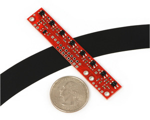
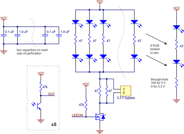
The Pololu QTR-8A and QTR-8RC reflectance sensor arrays are intended as line sensors, but they can be used as a general-purpose proximity or reflectance sensors. Each module is a convenient carrier for eight IR emitter and receiver (phototransistor) pairs evenly spaced at intervals of 0.375" (9.525 mm). The outputs are all independent, but the LEDs are arranged in pairs to halve current consumption. The LEDs are controlled by a MOSFET with a gate normally pulled high, allowing the LEDs to be turned off by setting the MOSFET gate to a low voltage. Turning the LEDs off might be advantageous for limiting power consumption when the sensors are not in use or for varying the effective brightness of the LEDs through PWM control.
The LED current-limiting resistors for 5 V operation are arranged in two stages; this allows a simple bypass of one stage to enable operation at 3.3 V. The LED current is approximately 20-25 mA, making the total board consumption just under 100 mA. The schematic diagram of the module is shown below:
 |
Specifications for the QTR-8x Reflectance Sensor Array
- Dimensions: 2.95" x 0.5"
- Operating voltage: 3.3-5.0 V
- Supply current: 100 mA
- Output format for the QTR-8A: 8 analog voltages ranging from 0 V to supplied voltage
- Output format for the QTR-8RC: 8 digital I/O-compatible signals that can be read as a timed high pulse
- Optimal sensing distance: 0.125" (3 mm)
- Maximum recommended sensing distance for the QTR-8A: 0.25" (6 mm)
- Maximum recommended sensing distance for the QTR-8RC: 0.375" (9.5 mm)
- Weight without header pins: 0.11 oz (3.1 g)
2. Contacting Pololu
You can check the QTR-8A page or QTR-8RC page for additional information. We would be delighted to hear from you about any of your projects and about your experience with the QTR-8A reflectance sensor array. You can contact us directly or post on our forum. Tell us what we did well, what we could improve, what you would like to see in the future, or anything else you would like to say!
3. Physical Characteristics
Both the QTR-8A and QTR-8RC have the same physical characteristics. Each array measures 2.95" long by 0.50" wide and has a maximum thickness of approximately 0.125". Without header pins, the unit weighs 0.11 oz (3.1 g). The individual reflectance sensors are distributed evenly on the board at 0.375" intervals. The mounting holes are intended for #2 screws.
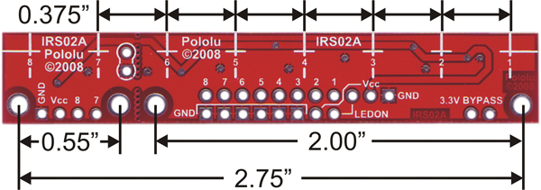 |
QTR-8A and QTR-8RC reflectance sensor array dimensions. |
|---|
4. Distinguishing the QTR-8A from the QTR-8RC
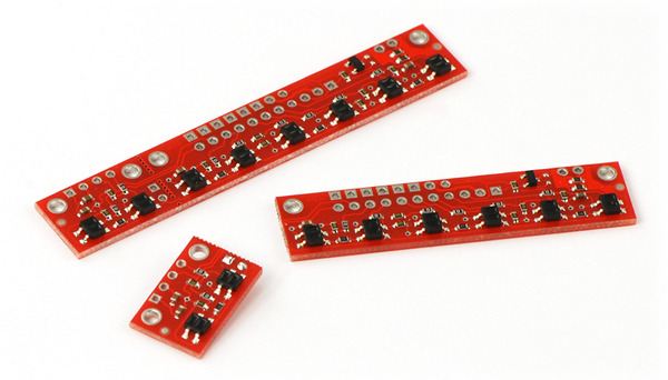
The QTR-8A sensor array has a different output format from the QTR-8RC, so it is important you know which sensor model you have. What distinguishes one model from another are the components placed on a common PCB. The pictures below show the two models:
 |
QTR-8A reflectance sensor array. |
|---|
 |
QTR-8RC reflectance sensor array. |
|---|
The QTR-8A uses a voltage divider for each sensor’s output while the QTR-8RC uses an RC circuit. This produces the most visible difference between the two: eight 47k voltage divider resistors (black components with “473” written on them in yellow) on the QTR-8A are replaced by capacitors (tan components) on the QTR-8RC.
5. Module Connections
The QTR-8x reflectance sensor arrays are designed to provide some connection flexibility. The pins are standard 0.1" spacing and are arranged to support connection using either an 11×1 header strip or an 8×2 header strip. A 25-pin 0.1" header strip is included with the module; you can break this strip into smaller strips and solder them as desired, or you can solder wires directly to the unit for a more compact installation. The two connection methods are pictured below:
 |
QTR-8x reflectance sensor array with 11×1 connection pins labeled. |
|---|
 |
QTR-8x reflectance sensor array with 8×2 connection pins labeled. |
|---|
Several pins appear in multiple locations, but you can leave duplicate connection points disconnected. For example, you do not need to connect ground to all six ground pins along the lower edge of the board. Duplicate pins exist so that you can choose the most convenient points to make your connections.
Vcc, GND, and 3.3V BYPASS
The Vcc and GND pins are where the sensor array receives its power. Your Vcc connection must be between 3.3 and 5 V and must be able to supply at least 100 mA. The sensor’s outputs will be relative to GND.
The module is calibrated so that its IR LEDs will achieve optimal brightness when Vcc is 5 V; using a lower Vcc will decrease the LED brightness or cause them to turn off completely. You can compensate for this by shorting the two 3.3V BYPASS pins together, which bypasses one stage of the LED current-limiting resistors and increases LED brightness.
Note: Do not short the 3.3V BYPASS pins together while using a Vcc of 5 V. While this would make the LEDs even brighter, it would exceed their current rating and put them at risk of burning out.
LEDON
This pin is connected to a MOSFET that delivers power to the IR LEDs, so its state determines the whether the LEDs are on or off. When this pin is driven high or left disconnected (it is internally pulled high), the LEDs are all on; when this pin is driven low, the LEDs are off. You can use this pin to save power by turning the LEDs off while you are not taking a reading. Additionally, you can connect this pin to a high-frequency PWM to control effective LED brightness and decrease power consumption.
QTR-8A Sensor Outputs
The QTR-8A reflectance sensor array has eight distinct sensor outputs, one from each LED/phototransistor pair. These outputs are analog voltages ranging from 0 V to Vcc (which must be between 3.3 and 5 V). With a strong reflectance, such as when the sensor is over a white surface, its output voltage will tend towards 0 V; with very weak reflectance, such as when the sensor is over a black surface, its output voltage will tend towards Vcc. To get a good range of readings between white and black surfaces, we recommend you mount your sensor no more than 0.25" away from the surface. In our tests, the optimal distance between the sensor and the surface has been 0.125". Please see our QTR Sample Output Data document for more information.
QTR-8RC Sensor Outputs
The QTR-8RC reflectance sensor array also has eight distinct sensor outputs, one from each LED/phototransistor pair. In the 8RC sensor model, each phototransistor uses a capacitor discharge circuit that allows a digital I/O line on a microcontroller to take an analog reflectance reading by timing how long it takes the output voltage to decay due to the phototransistor. This format has several advantages over the 8A sensor model:
- No analog-to-digital converter (ADC) is required
- Improved sensitivity over voltage-divider analog output
- Parallel reading of all eight sensors is possible with most microcontrollers
- Parallel reading allows optimized use of LED power enable option
When you have a microcontroller digital I/O connected to a sensor output, the typical sequence for reading that sensor is:
- Turn on IR LEDs (optional).
- Set the I/O line to an output and drive it high.
- Allow at least 10 μs for the sensor output to rise.
- Make the I/O line an input (high impedance).
- Measure the time for the voltage to decay by waiting for the I/O line to go low.
- Turn off IR LEDs (optional).
These steps can typically be executed in parallel on multiple I/O lines.
With a strong reflectance, such as when a sensor is over a white surface, the decay time can be as low as several dozen microseconds; with very weak reflectance, such as when the sensor is over a black surface, the decay time will typically be a few milliseconds, but can be several dozen milliseconds in the worst case. The exact time of the decay depends on your microcontroller’s I/O line characteristics. Meaningful results can be available within 1 ms in typical cases (i.e. when not trying to measure subtle differences in low-reflectance scenarios), allowing up to 1 kHz sampling of all 8 sensors. If lower-frequency sampling is sufficient, substantial power savings can be realized by using the LEDON pin to turn off the LEDs. For example, if a 100 Hz sampling rate is acceptable, the LEDs can be off 90% of the time, lowering average current consumption from 100 mA to 10 mA.
If you want to achieve high frequency sampling rates, we recommend you mount your sensors 0.125" away from the surface. The greater your distance from the surface, the lower the overall reflectance will be, which in turn will result in longer decay times. We recommend you mount your sensors no more than 0.375" away from the surface. Please see our Pololu QTR Reflectance Sensor Application Note for more information.
6. Breaking into Two Submodules
If you don’t need or cannot fit all eight sensors, the QTR-8x arrays can each be separated into two smaller sensor arrays that can function independently: a two-sensor array and a six-sensor array.
 |
To break the board, use a sharp knife (e.g. hobby knife or box cutter) to score along the perforation (row of vias) between sensors 6 and 7. Place the long side of board on a flat surface with an edge, such as a table, so the perforation lines up with the edge. Hold the board against the table and press firmly down on the overhanging piece until it snaps off. If it doesn’t feel like the PC board is breaking, make the score deeper. You might want to file the broken edges of the boards.
Once the board is broken, you will need to modify the small piece slightly before it becomes functional. If you are operating at a Vcc of 5 V, solder the 100 Ohm through-hole resistor that was included with your QTR-8x across the two pins as shown below:
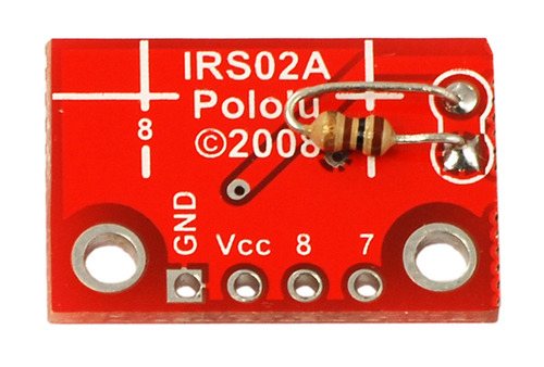 |
If you are operating at a Vcc of 3.3 V, short those two pins together with a piece of wire. With a connection in place between these two pins, the two-sensor board will function.
After the separation, sensor outputs 7 and 8 on the six-sensor board will no longer provide any signals.
7. Additional Considerations
As the sensing distance of your sensors increases, the distinction between black and white surfaces starts to decrease. This problem can be exacerbated by infrared components of ambient lighting. The QTR-8x PCB was designed to help shield the sensors from ambient IR, but this may not be sufficient for areas with unusually high ambient IR or in cases where you need to mount your QTR-8x higher than the recommended 0.25" maximum. In these situations, you might fight it helpful to use shielding (e.g. a skirt around your robot) to block ambient IR.
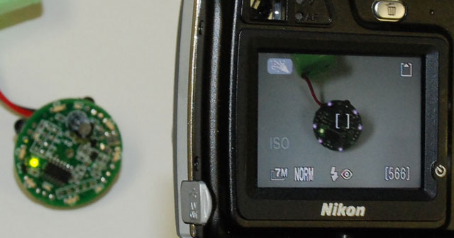
When troubleshooting your QTR-8x, a digital camera can be useful in determining whether the IR LEDs are functioning as expected. Many older/cheaper digital cameras lack IR filters (most cell phone cameras fit in this category) and can therefore be used to determine if the LEDs are on or off. However, some cameras (usually more expensive ones) have better filters that block IR. In the picture below, a point-and-shoot camera shows the IR LEDs of our IR Beacon shining (in purple) but the DSLR with which the picture is taken does not show the LEDs.
 |


