Pololu Blog »
New product: 5V, 2.5A Step-Down Voltage Regulator D24V25F5
Just about every integrated switching regulator datasheet I come across advertises how easy it is to use the chip, which is probably a good sign that it’s not necessarily that easy. I have designed several of our regulator boards, and for the most part, following the manufacturer recommendations and warnings about short traces and small loops led to working designs without much drama. But, as we push for higher performance, it can get tricky, and I thought I would share some fun pictures of what goes into troubleshooting a design that ought to work but did not.
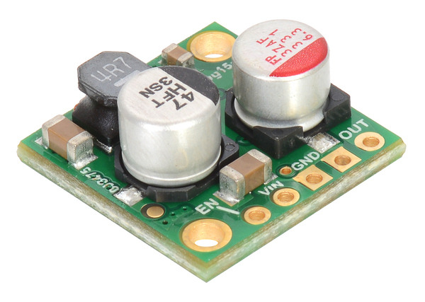
This instance is about the D24V25F5 step-down regulator we just released today. It should have been straightforward because the basic circuit is very similar to that of the higher-power D24V60F5 and D24V90F5 regulators we released earlier this year. Because this board was supposed to be really small, I designed it with components tightly packed on both sides, which meant I had to make compromises on some of those trace lengths and loop sizes. It wasn’t even clear that the circuit would be routable with just two PCB layers, so when I did find a solution, the design team wanted to try it even though we knew we were pushing our luck.
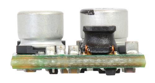 |
Pololu 2.5A Step-Down Voltage Regulator D24V25Fx, side view. |
|---|
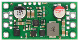
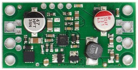
Well, if we had been lucky, you might have been reading a less interesting version of this new product announcement three weeks ago. As is typical for these borderline cases, it was the especially hope-dashing kind of failure where a casual test indicated that the board was working, but more in-depth tests revealed stability and performance issues. To make sure the components were not the source of the problem, we put the exact same components onto the PCB of the larger version that already worked. The pictures below show the D24V60F5 regulator (left) populated with its standard components and the D24V60F5 regulator’s PCB populated with the components for the new D24V25F5 (right).
|
|
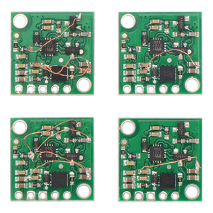
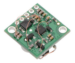
The new components on the old board worked, so after some final checks that the new prototypes were assembled correctly, we knew it was a layout issue. We wanted assurance that the design could work before just diving into a four-layer revision, so I took some prototypes and added redundant connections to see their impact. The pictures below show some of my test boards with varying numbers of additional ground connections.
|
|
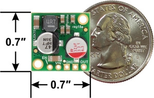 |
I was able to see that the more additional ground connections there were, the more the issues went away. So, I routed the four-layer board, and after a week of tests on over a dozen prototypes, I am happy to announce the release of our most sophisticated regulator yet! The D24V25F5 buck regulator generates 5 V from input voltages of up to 38 V with typical efficiencies of 85% to 95%. The board measures only 0.7″ × 0.7″, but it allows a typical continuous output current of up to 2.5 A.
We are quite happy with how manufacturing of these units is going, so we expect to be moving toward more dense designs like this in future products.
