
This is a merged information page for Item #1593.
View normal product page.
Pololu item #:
1593
Brand:
PCX
Status:
Special Order Only

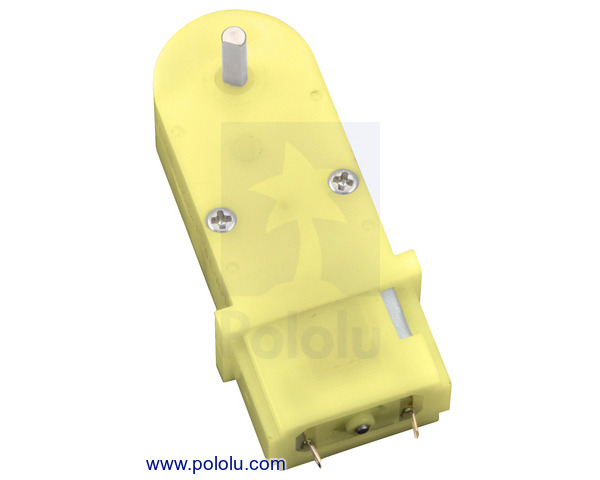
This compact, inexpensive plastic gearmotor (brushed DC motor with a 180:1 reduction gearbox) is well suited for use in small robots. While intended for operation at 4.5 V, it should run comfortably in the 3 V to 6 V range. The gearbox has a 9.7mm-long, 3 mm-diameter D-shaped output shaft that is perpendicular to the motor shaft, and a built-in safety clutch helps protect the gears from excessive loads.
Key specifications:
| voltage | no-load performance | stall extrapolation |
|---|---|---|
| 4.5 V | 80 RPM, 80 mA | 2.2 kg⋅cm (30 oz⋅in), 800 mA |
Alternatives available with variations in these parameter(s): shaft type no-load speed @ 4.5V extended motor shaft? Select variant…
 Compare all products in Mini Plastic Gearmotors.
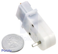 |
Mini plastic gearmotor 90-degree 3mm D-shaft output. |
|---|
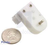 |
Mini plastic gearmotor offset 3mm D-shaft output with U.S. quarter for size reference. |
|---|
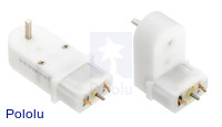 |
120:1 mini plastic gearmotors with extended motor shafts. |
|---|
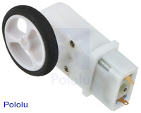 |
Mini Plastic Gearmotor, 90° 3mm D-Shaft Output with Pololu Wheel 32×7mm. |
|---|
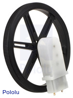 |
Mini Plastic Gearmotor, 90° 3mm D-shaft Output with Pololu Wheel 90×10mm. |
|---|
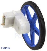 |
Mini plastic gearmotor offset 3mm D-shaft output with Pololu wheel. |
|---|
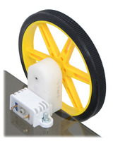 |
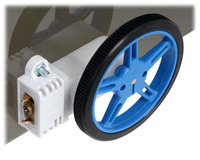
80×10mm Pololu wheel and offset mini plastic gearmotor mounted with a wide mini plastic gearmotor bracket. |
|---|
 |
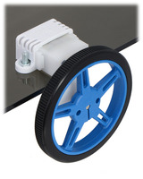
60×8mm Pololu wheel and 90° mini plastic gearmotor mounted with a wide mini plastic gearmotor bracket (with spacer). |
|---|
 |
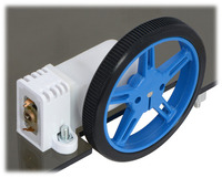
60×8mm wheel and offset mini plastic gearmotor mounted with a wide mini plastic gearmotor bracket. |
|---|
 |
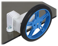
60×8mm Pololu wheel and 90° mini plastic gearmotor mounted with tall mini plastic gearmotor bracket (with spacer). |
|---|
 |
60×8mm Pololu wheel and offset mini plastic gearmotor mounted with a tall mini plastic gearmotor bracket (with spacer). |
|---|
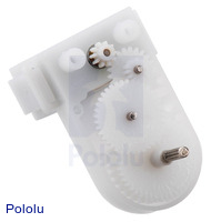 |
Gears inside the mini plastic gearmotor with offset output shaft (2mm spline version). |
|---|
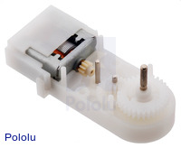 |
Gears inside the mini plastic gearmotor with 90 degree output (2mm spline version). |
|---|
These brushed DC gearmotors are compact and affordable — perfect for building a quick, miniature robot. They are intended for use at 4.5 V, though in general, these kinds of motors can run at voltages above and below this nominal voltage, so they should operate comfortably in the 3 V to 6 V range (rotation can start at voltages as low as 0.5 V). Lower voltages might not be practical, and higher voltages could start negatively affecting the life of the motor. The plastic gearbox is protected by a built-in safety clutch that will typically slip before the gear teeth can shear (typically when the load exceeds around 25 oz-in, or 2 kg-cm).
The mini plastic gearmotor family offers two output shaft orientations relative to the motor shaft (offset and 90°), two motor options (normal and high-power, or HP for short), and two gearbox options (120:1 and 180:1). The 120:1 versions are white and the 180:1 versions are yellow:
|
|
Some versions of these gearmotors are also available with an additional 1.5 mm-diameter output shaft that protrudes from the rear of the motor. This 5 mm-long rear shaft rotates at the same speed as the input to the gearbox and offers a way to add an encoder, such as our magnetic encoder for mini plastic gearmotors, to provide motor speed or position feedback:
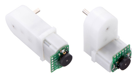 |
Magnetic Encoder Kit for Mini Plastic Gearmotors assembled on mini plastic gearmotors with extended motor shafts. |
|---|
| Motor Type | Stall Current @ 4.5 V |
No-Load Speed @ 4.5 V |
Stall Torque @ 4.5 V |
 90° output |
 90° output + motor shaft |
 offset output |
 offset output + motor shaft |
|---|---|---|---|---|---|---|---|
| high-power (HP) |
1250 mA | 150 RPM | 25 oz-in | 120:1 mini HP | 120:1 mini HP | 120:1 mini HP | 120:1 mini HP |
| low-power | 800 mA | 120 RPM | 20 oz-in | 120:1 mini | 120:1 mini | 120:1 mini | 120:1 mini |
| 80 RPM | 30 oz-in | 180:1 mini | 180:1 mini |
Note: The stall torque values listed are approximate, and the built-in safety clutch might start slipping at lower torques.
The gearmotors in the table above all have a 3 mm diameter D-shaft output. These shafts are just like the ones on our micro metal gearmotors and are compatible with many Pololu wheels and our 3 mm universal mounting hubs. We also carry two low-power, 120:1 mini plastic gearmotors with 2 mm diameter spline outputs: 90° 2mm spline output and offset 2mm spline output. These gearmotors all work with our wide and tall mounting brackets for mini plastic gearmotors.
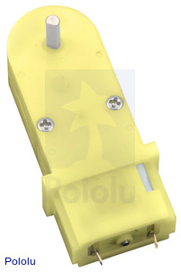
This item has a low-power motor (800 mA stall current), a 180:1 gearbox, and a 3 mm diameter “D”-shaped output shaft that is perpendicular to the motor shaft. The motor shaft does not extend past the base of the motor. See the dimension diagram (75k pdf) of this gearmotor for more information.
Exact gear ratio: ``(22×38×44×31×30) / (10×11×11×17×9) ~~ bb(184.78)``
 |
|
|
|
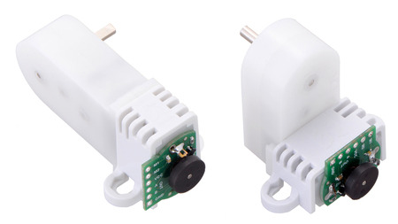 |
The Magnetic Encoder Kit for Mini Plastic Gearmotors works with our Tall (left) and Wide (right) Mini Plastic Gearmotor Brackets. |
|---|
|
|
|
|
|
The 120:1 gear ratio versions have white plastic bodies and the 180:1 gear ratio versions have yellow plastic bodies (see the main product picture).
| Size: | 54.5 x 20 x 13.8 mm1 |
|---|---|
| Weight: | 19.5 g |
| Shaft diameter: | 3 mm |
| Shaft type: | 90° 3mm D |
|---|---|
| Typical operating voltage: | 4.5 V |
| Gear ratio: | 180:1 |
| No-load speed @ 4.5V: | 80 rpm |
| No-load current @ 4.5V: | 80 mA |
| Stall current @ 4.5V: | 800 mA |
| Stall torque @ 4.5V: | 30 oz·in2 |
| Extended motor shaft?: | N |
Dimension diagram of the mini plastic gearmotor with 90° 3mm D-shaft output.
Dimension diagram of the mini plastic gearmotor with 90° 3mm D-shaft output and extended motor shaft.
Dimension diagram of the mini plastic gearmotor HP with 90° 3mm D-shaft output and extended motor shaft.
Dimension diagram of the mini plastic gearmotor with offset 3mm D-shaft output.
Dimension diagram of the mini plastic gearmotor with offset 3mm D-shaft output and extended motor shaft.
Dimension diagram of the mini plastic gearmotor HP with offset 3mm D-shaft output and extended motor shaft.
This MATLAB script, written by Ali Asgher Mansoor Habiby, plots speed, power, current draw, and efficiency as they vary with torque when you input the gearmotor specifications. It also prints the resistance of the motor, and the current draw and torque at which maximum efficiency and maximum power occur.
No; the information we have available for this motor can be found on its product page. However, you can approximate various additional motor parameters from the information found in the “Specs” tab.
The electrical resistance of the motor can be approximated by dividing the rated voltage by the stall current (at the rated voltage). The electromotive force constant (Ke) can be approximated by dividing the rated voltage by the free-run speed (at the rated voltage). To approximate the motor torque constant (Kt), you can divide the stall torque by the stall current.
For pretty much any DC motor, the current, speed, power, and efficiency curves as a function of torque will look like those in the graph below (assuming motor voltage and temperature are constant):
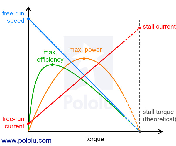 |
The current and speed curves are approximately linear, and the product pages for our motors provide the approximate end points for these lines: (0 torque, no-load current) and (stall torque, stall current) for the red line, and (0 torque, no-load speed) and (stall torque, 0 speed) for the blue line.
The orange output power curve is the product of the speed and the torque, which results in an inverted parabola with its peak at 50% of the stall torque.
The green efficiency curve is the output power divided by the input power, where the input power is current times voltage. The voltage is constant, so you can divide the output power curve by the current line to get the general shape of the efficiency curve, which in turn lets you identify the torque, speed, and current that correspond to max efficiency.
There are many programs out there that you can use to generate these curves. For example, if you have access to MATLAB, you can use this customer-created MATLAB script to generate these motor plots for you from the specifications we provide for each gearmotor.
Note: A good general rule of thumb is to keep the continuous load on a DC motor from exceeding approximately 20% to 30% of the stall torque. Stalling gearmotors can greatly decrease their lifetimes, occasionally resulting in immediate damage to the gearbox or thermal damage to the motor windings or brushes. Do not expect to be able to safely operate a brushed DC gearmotor all the way to stall. The safe operating range will depend on the specifics of the gearmotor itself.
No blog posts to show.