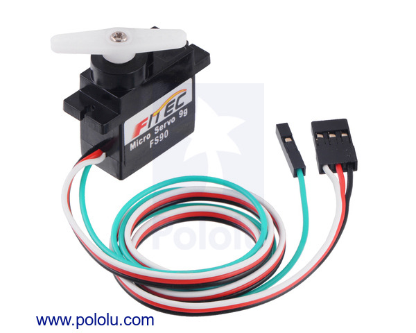

This is a merged information page for Item #3436.
View normal product page.
Pololu item #:
3436
Brand:
FEETECH

This version of the FS90 micro servo from FEETECH is specially modified to provide access to the feedback potentiometer through a fourth (green) wire, allowing you to directly measure the position of the output. This extra information enables more complex robotics applications, such as determining when the servo has reached its target, detecting when the output is blocked, or implementing your own higher-level closed-loop position control.
Key specs at 6 V: 0.10 sec/60°, 21 oz-in (1.5 kg-cm), 13 g.
 Compare all products in RC Servos or
  FEETECH Servos or
  FEETECH Servos with Feedback.
 |
FEETECH FS90-FB Micro Servo with Position Feedback. |
|---|
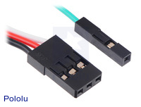 |
Servo and feedback connectors on the FEETECH servos with position feedback. |
|---|
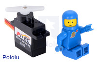 |
FEETECH FS90 Micro Servo with a LEGO Minifigure as a size reference. |
|---|
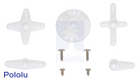 |
An example of hardware included with the FEETECH FS90 and FS90R micro servos. Actual hardware might vary. |
|---|
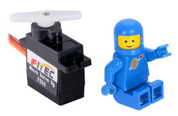 |
FEETECH FS90 Micro Servo with a LEGO Minifigure as a size reference. |
|---|
The FS90-FB is a specially modified version of FEETECH’s FS90 micro analog servo that provides access to the feedback potentiometer through a fourth (green) wire, which makes it possible to directly measure the output angle. With this extra information, you can determine when the servo has reached its target position (or detect if something is interfering with its ability to get there). This feedback also enables more complex closed-loop control of the servo from your main controller.
Like the FS90, the FS90-FB works with standard RC servo pulses, providing a running angle of approximately 120° over a servo pulse range of 900 µs to 2100 µs. As with most servos, the pulse range can be expanded to achieve an expanded operating angle, but the limits of this are not specified by FEETECH. The feedback voltage varies linearly over this range by a couple of volts.
The servo signal, power, and ground are provided through an extra-long 3-wire servo cable that is terminated with a standard JR-style connector, which is Futaba-compatible. The feedback is accessible through a separate green wire that is terminated like our female premium jumper wires and works with standard 0.1″ male header pins. These cables are approximately 15″ (38 cm) long (which is almost twice as long as the cables on the standard FS90).
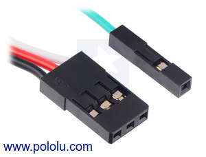 |
Servo and feedback connectors on the FEETECH servos with position feedback. |
|---|
For more information about this servo, see the FS90 datasheet (69k pdf) (please note that this is the datasheet for the standard FS90, so it does not include any information about the special feedback modification, and the specified cable length does not apply).
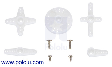
The following picture shows an example of the hardware that might be included (actual hardware could vary):
 |
Note that as with most hobby servos, stalling or back-driving this servo can damage it.
Two versions of this servo are available. This product is the FS90, which offers closed-loop position control over a limited range. Alternatively, the FS90R is specifically designed to be a continuous-rotation micro servo that offers open-loop speed control. The FS90 and FS90R have identical dimensions and use the same motor, so the FS90 will also work with our 60×8mm wheel for the FEETECH FS90R.
| Size: | 23.2 × 12.5 × 22 mm |
|---|---|
| Weight: | 13 g |
| Digital?: | N |
|---|---|
| No-load current @ 6V: | 200 mA |
| Stall current @ 6V: | 600 mA1 |
| Speed @ 6V: | 0.10 sec/60° |
| Stall torque @ 6V: | 1.5 kg·cm |
| Speed @ 4.8V: | 0.12 sec/60° |
| Stall torque @ 4.8V: | 1.3 kg·cm |
| Hardware included?: | Y |
| Lead length: | 15 in |
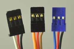 |
Most standard radio control (RC) servos have three wires, each a different color. Usually, they are either black, red, and white, or they are brown, red, and orange/yellow:
Please check the specs for your servo to determine the proper power supply voltage, and please take care to plug the servo into your device in the proper orientation (plugging it in backwards could break the servo or your device).
Note: Some of the servos we carry also have an optional fourth green wire that is separate from the three standard ones. This wire provides access to the feedback potentiometer, allowing you to directly measure the position of the output. The servos with this extra wire have "with Position Feedback" at the ends of their product names. The picture below is an example of such a servo.
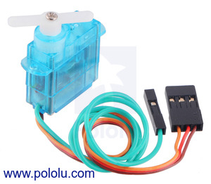 |
FEETECH Sub-Micro Servo FS0403-FB with Position Feedback. |
|---|
We do not specify the range of rotation of our servos because this information is not generally available from servo manufacturers. RC servos are usually intended for controlling things like the steering mechanism in an RC car or the flaps on an RC plane. Manufacturers make sure that the range is enough for these typical applications, but they do not guarantee performance over a wider range.
This means most RC servos will rotate about 90° using the standard 1–2 ms pulse range used by most RC receivers. However, if you are using a controller capable of sending a wider range of pulses, many servos can rotate through almost 180°.
You can find a servo’s limits if you use a servo controller that can send pulses outside of the standard range (such as our Maestro servo controllers). To find the limits, use the lowest possible supply voltage at which the servo moves, and gradually increase or decrease the pulse width until the servo does not move any further or you hear the servo straining. Once the limit is reached, immediately move away from it to avoid damaging the servo, and configure your controller to never go past the limit.
You might be wondering why we do not just follow the above steps for all the servos we carry and list a specification for degrees of rotation. Unfortunately, since servo manufacturers do not specify the range of rotation, it might change from one manufacturing run to the next. They will not inform us about changes that are not specified, and we have no way of knowing if or when they might change their manufacturing process.
For more information about servos and how to control them, we recommend the series of blog posts on servos starting with: Introduction to servos.
We are excited to announce the newest additions to our selection of servos: FEETECH FS90-FB Micro Servo with Position Feedback...