

This is a merged information page for Item #2452.
View normal product page.
Pololu item #:
2452
Brand:
Pololu
Status:
Active and Preferred

This board is a simple carrier of Allegro’s ACS711KEXLT-15AB-T Hall effect-based, electrically isolated current sensor, which offers a low-resistance (~0.6 mΩ) current path and a 100 kHz bandwidth for fast response times.
| Part Suffix | Range | Sensitivity @ 3.3 V | Zero Point @ 3.3 V | Fault Trip Level | Supply Voltage |
|---|---|---|---|---|---|
| KEXLT-15AB-T | ±15.5 A (bidirectional) | 90 mV/A | 1.65 V | ±15.5 A | 3 V to 5.5 V |
Alternatives available with variations in these parameter(s): current range Select variant…
 Compare all products in ACS711 Current Sensor Carriers.
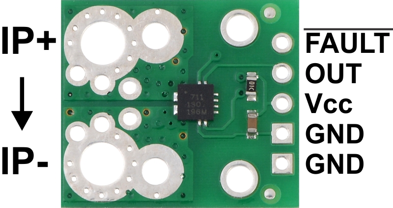 |
ACS711EX current sensor carrier pinout. |
|---|
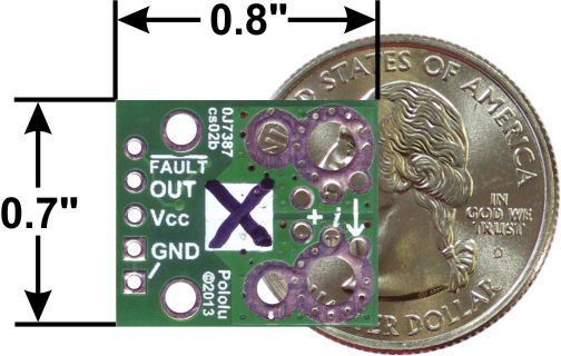 |
ACS711EX current sensor carrier -15.5A to +15.5A back with dimensions. |
|---|
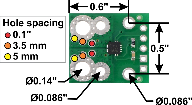 |
ACS711EX current sensor carrier connection and mounting dimension diagram. |
|---|
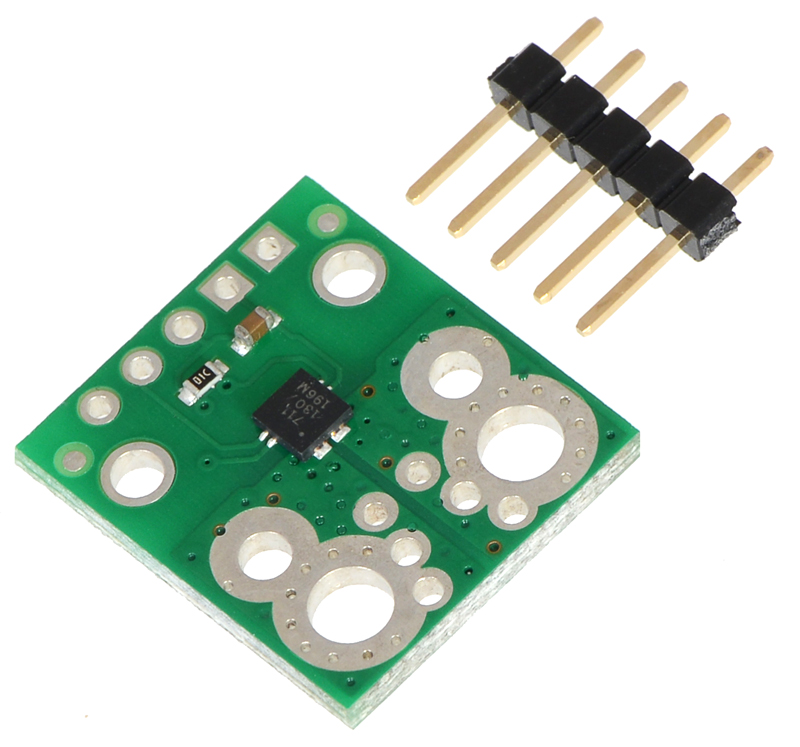 |
ACS711EX current sensor carrier with included 5 × 1 0.1″ header pins. |
|---|
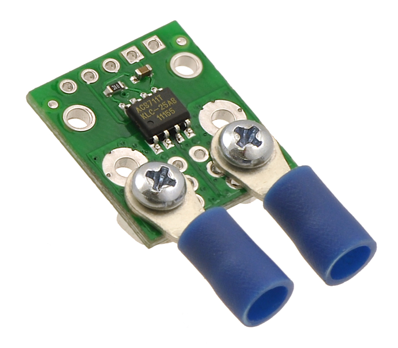 |
ACS711 current sensor carrier (LC package version) with solderless ring terminal connectors (not included). |
|---|
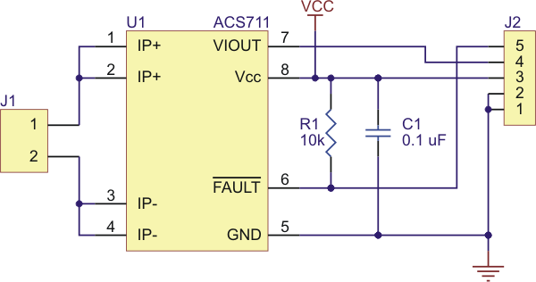 |
ACS711 current sensor carrier schematic diagram. |
|---|
 |
|
|
We are offering these breakout boards with support from Allegro Microsystems as an easy way to use or evaluate their ACS711 Hall effect-based, electrically isolated current sensors with overcurrent fault output; we therefore recommend careful reading of the ACS711 datasheet before using this product. This sensor has an operating voltage of 3 V to 5.5 V and an output sensitivity of 90 mV/A when Vcc is 3.3 V (or 136 mV/A when Vcc is 5 V). The following list details some of the sensor’s key features:
The pads are labeled on the bottom silkscreen, as shown in the picture to the right. The silkscreen also shows the direction that is interpreted as positive current flow via the +i arrow.
This 15.5 A current sensor is marked with a black X. We also sell a 31 A version that uses the same carrier PCB; you can distinguish the versions by reading the text on the IC or by looking at the color of the X on the bottom silkscreen.
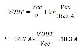
The sensor requires a supply voltage of 3 V to 5.5 V to be connected across the Vcc and GND pads, which are labeled on the bottom silkscreen. The sensor outputs an analog voltage that is linearly proportional to the input current. The quiescent output voltage is Vcc/2 and changes by 90 mV per amp of input current (when Vcc = 3.3 V), with positive current increasing the output voltage and negative current decreasing the output voltage. The relationship between the instantaneous input current, i, and sensor output voltage, VOUT, can be represented by the following equations:
 |
The FAULT pin is normally high and latches low when the current exceeds ±15.5 A. Once the FAULT pin is latched low, the only way to reset it is by toggling power on the Vcc pin. In our tests, this module was able to handle 15 A of continuous current without exceeding 50°C, with no cooling beyond the heat dissipation of the PCB.
|
|
The input current can be connected to the board in a variety of ways. Holes with 0.1″, 3.5 mm, and 5 mm spacing are available as shown in the diagram above for connecting male header pins or terminal blocks. For high-current applications, you can solder wires directly to the through-holes that best match your wires, or you can use solderless ring terminal connectors, as shown in the picture above. The large through-holes are big enough for #6 screws.
Warning: This product is intended for use below 30 V. Working with higher voltages can be extremely dangerous and should only be attempted by qualified individuals with appropriate equipment and experience.
The board has two mounting holes on the logic side of the board. These mounting holes are 0.5″ apart and are designed for #2 screws.
This board ships assembled with all surface mount components, and a 5×1 strip of 0.1″ header pins is included but not soldered in, as shown in the picture below.
|
ACS711EX current sensor carrier with included 5 × 1 0.1″ header pins. |
|---|
|
ACS711 current sensor carrier schematic diagram. |
|---|
The dimension diagram is available as a downloadable PDF (273k pdf).
We have a variety of current sensors available with different ranges, sensitivities, and features. You can use the following table to compare our options:
 |
 |
 |
 |
 |
 |
 |
 |
|
|---|---|---|---|---|---|---|---|---|
| CT220 Contactless Current Sensor Carriers |
ACS3704x Current Sensor Micro Carriers |
ACS3704x Current Sensor Compact Carriers |
ACS711 Current Sensor Carriers |
ACS71240 Current Sensor Carriers |
ACS724 Current Sensor Carriers |
ACS37030 Current Sensor Compact Carriers |
ACS37220 Current Sensor Compact Carriers |
|
| Allegro Sensor | CT220xMV-HS5 | ACS3704x | ACS711KEXT | ACS71240 | ACS724LLCTR | ACS37220 | ACS37030 | |
| Sensing technology | XtremeSense™ TMR (tunneling magnetoresistance) |
Hall effect | Hall effect | Hall effect | Hall effect | Hall effect + inductive coil | Hall effect | |
| Logic voltage range | 2.7–5.5 V | 3.3V versions: 3.0–3.6 V 5V versions: 4.75–5.5 V |
3.0–5.5 V | 3.3V ver: 3.0–3.6 V 5V ver: 4.5–5.5 V |
4.5–5.5 V | 3.0–3.6 V | 3.3V ver: 3.15–3.45 V 5V ver: 4.5–5.5 V |
|
| Family current range | 10–800 A | 10–30 A | 15.5–31 A | 10–50 A | 2.5–50 A | 20–65 A | 100–200 A | |
| Range/sensitivity of individual versions | (2) ±1.5 mT / 1500 mV/mT ±15 mT / 150 mV/mT |
ACS37041: 3.3V Bidirectional: ±10 A / 132 mV/A ±30 A / 44 mV/A 5V Bidirectional: ±10 A / 200 mV/A ±30 A / 66.7 mV/A ACS37042: 3.3V Bidirectional: ±10 A / 132 mV/A ±30 A / 44 mV/A 5V Bidirectional: ±10 A / 200 mV/A ±30 A / 66.7 mV/A |
ACS37041: 3.3V Bidirectional: ±10 A / 132 mV/A ±30 A / 44 mV/A 5V Bidirectional: ±10 A / 200 mV/A ±30 A / 66.7 mV/A ACS37042: 3.3V Bidirectional: ±10 A / 132 mV/A ±30 A / 44 mV/A 5V Bidirectional: ±10 A / 200 mV/A ±30 A / 66.7 mV/A |
Bidirectional:(1) ±15.5 A / 90 mV/A ±31 A / 45 mV/A |
3.3V Bidirectional: ±10 A / 132 mV/A ±30 A / 44 mV/A ±50 A / 26.4 mV/A 5V Bidirectional: ±10 A / 200 mV/A ±30 A / 66 mV/A ±50 A / 40 mV/A 5V Unidirectional: 0–50 A / 80 mv/A |
5V Bidirectional:(2) ±2.5 A / 800 mV/A ±5 A / 400 mV/A ±10 A / 200 mV/A ±20 A / 100 mV/A ±30 A / 66 mV/A ±50 A / 40 mV/A 5V Unidirectional:(2) 0–5 A / 800 mv/A 0–10 A / 400 mv/A 0–20 A / 200 mv/A 0–30 A / 133 mV/A |
3.3V Bidirectional: ±20 A / 66 mV/A ±40 A / 33 mV/A ±65 A / 20.3 mV/A |
3.3V Bidirectional: ±100 A / 13.2 mV/A ±150 A / 8.8 mV/A 5V Bidirectional: ±100 A / 20 mV/A ±150 A / 13.3 mV/A ±200 A / 10 mV/A |
| IC current path resistance | N/A | 1.6 mΩ | 0.6 mΩ | 0.6 mΩ | 0.6 mΩ | 0.7 mΩ | 0.1 mΩ | |
| PCB | N/A | 2 layers, 1-oz copper |
2 layers, 2-oz copper |
2 layers, 2-oz copper |
2 layers, 2-oz copper |
2 layers, 2- or 4-oz copper(3) |
2 layers, 2-oz copper |
2 layers, 2-oz copper |
| Max bandwidth | 30 kHz | 150 kHz | 100 kHz | 120 kHz | 120 kHz(4) | 5 MHz | 150 kHz | |
| Size | 0.4″ × 0.62″ | 0.3″ × 0.4″ | 0.7″ × 0.8″ | 0.7″ × 0.8″ | 0.7″ × 0.8″ | 0.7″ × 0.8″ | 0.7″ × 0.8″ | 0.7″ × 0.8″ |
| Overcurrent fault output |
User-configurable threshold | |||||||
| Common-mode field rejection | ||||||||
| Nonratiometric output | ||||||||
| 1-piece price | $4.95 | $4.15 – $4.69 | $4.45 – $4.99 | $4.85 | $5.25 | $9.95 – $11.49 | $11.95 | $6.95 |
Note 1: Sensitivity when Vcc = 3.3 V; actual sensitivity is ratiometric (i.e. it is proportional to Vcc).
Note 2: Sensitivity when Vcc = 5 V; actual sensitivity is ratiometric (i.e. it is proportional to Vcc).
Note 3: 50A version of this carrier uses 4-oz copper PCB; all other versions of this carrier use 2-oz copper.
Note 4: Bandwidth can be reduced by adding a filter capacitor.
Note 1: Sensitivity when Vcc = 3.3 V; actual sensitivity is ratiometric (i.e. it is proportional to Vcc).
Note 2: Sensitivity when Vcc = 5 V; actual sensitivity is ratiometric (i.e. it is proportional to Vcc).
Note 3: 50A and higher versions of this carrier use a 4-layer PCB; all other versions of this carrier use a 2-layer PCB.
You can also use the following selection box to see these options sorted by current range:
Alternatives available with variations in these parameter(s): current range Select variant…
| Size: | 0.7″ × 0.8″ |
|---|---|
| Weight: | 1.0 g1 |
| Current sense: | 90 mV/A2 |
|---|---|
| Minimum logic voltage: | 3 V |
| Maximum logic voltage: | 5.5 V |
| Supply current: | 4 mA |
| Current range: | -15.5A to +15.5A (bidirectional 15.5A), 3-5.5V |
| Current sensor: | Allegro ACS711KEXLT-15AB |
| PCB dev codes: | cs02b |
|---|---|
| Other PCB markings: | 0J7387, white box with black X |
This DXF drawing shows the locations of all of the board’s holes.
Allegro product page for the ACS711, where you can find additional application notes and other resources.
No FAQs available.
No blog posts to show.


