

This is a merged information page for Item #2199.
View normal product page.
Pololu item #:
2199
Brand:
Pololu
Status:
Clearance

Clearance notice: These older current sensors are on clearance at a discounted price and will be discontinued once remaining component stock is depleted.
This board is a simple carrier of Allegro’s bidirectional ±75A ACS709 Hall effect-based linear current sensor with overcurrent fault output, which offers a low-resistance (~1.1 mΩ) current path and electrical isolation. The sensor has optimized accuracy for currents from -37.5 A to 37.5 A, and the analog voltage output is linear for current magnitudes up to 75 A. The ratiometric output voltage is centered at VCC/2 and has a typical error of ±2%. It operates from 3 V to 5.5 V, so it can interface directly to both 3.3 V and 5 V systems.
 Compare all products in Clearance Current Sensors.
 |
ACS709 current sensor carrier pinout. |
|---|
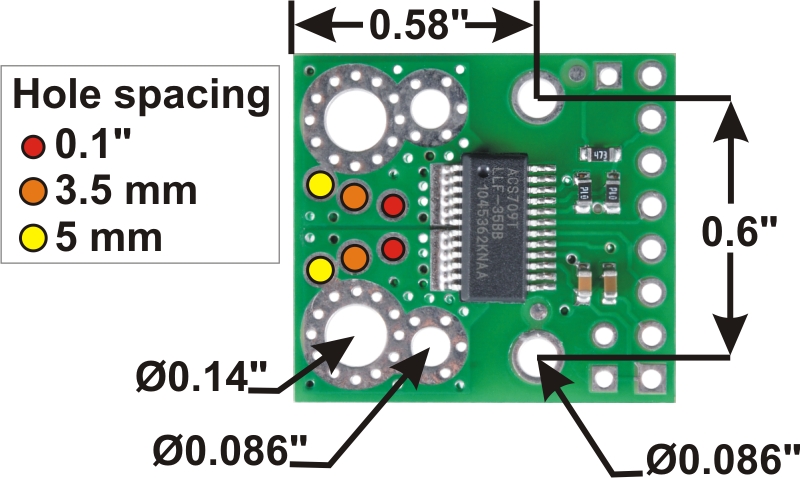 |
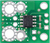
ACS709 current sensor carrier mounting holes and current inputs. |
|---|
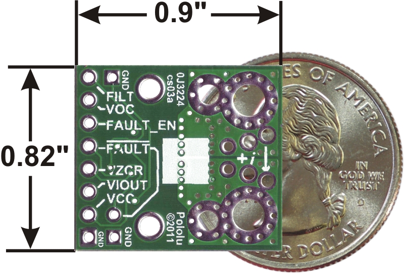 |
ACS709 current sensor carrier -75A to +75A back with dimensions. |
|---|
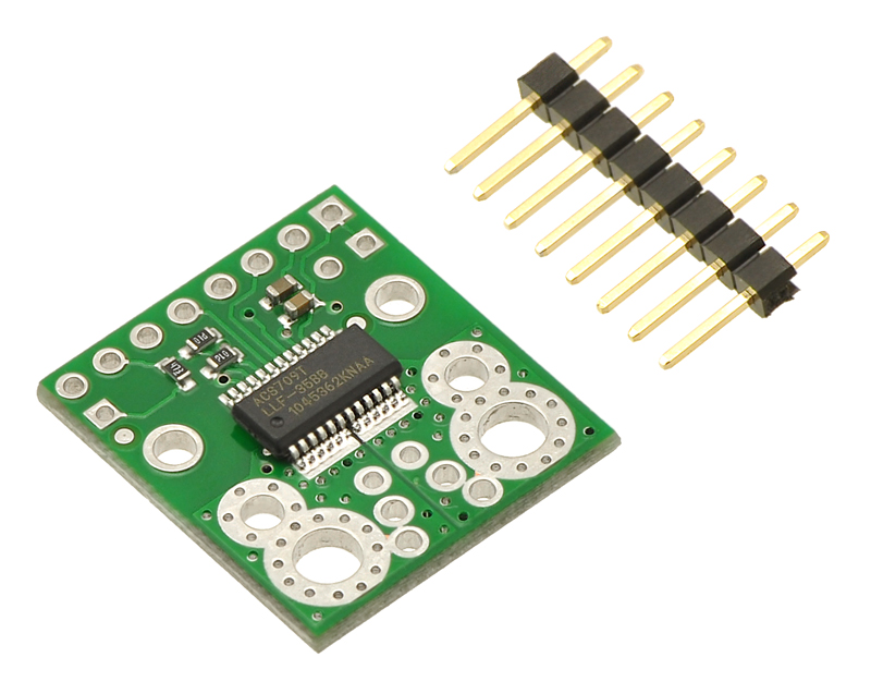 |
ACS709 current sensor carrier with included 8 × 1 0.1″ header pins. |
|---|
 |
ACS709 current sensor carrier with solderless ring terminal connectors (not included). |
|---|
 |
ACS709 current sensor carrier schematic diagram. |
|---|
|
This current sensor is a carrier board or breakout board for Allegro’s ACS709LLFTR-35BB-T Hall effect-based linear current sensor with overcurrent fault output; we therefore recommend careful reading of the ACS709 datasheet (1MB pdf) before using this product. The sensor has an operating voltage of 3 V to 5.5 V and an output sensitivity of 18.5 mV/A when Vcc is 3.3 V (or 28 mV/A when Vcc is 5 V). The following list details some of the sensor’s key features:
The pads are labeled on the bottom silkscreen, as shown in the picture above. The silkscreen also shows the direction that is interpreted as positive current flow via the +i arrow.
Note: The sensor’s extended -75 A to 75 A range should be limited to transient currents. In our tests, we found that the IC could tolerate 50 A for 20 seconds or 37.5 A for 150 seconds before exceeding its maximum temperature rating of 150°C. Therefore, unless you are taking special steps to keep the IC cool, we recommend limiting continuous currents to under 30 A. Even with a low conductive path resistance of 1.1 mΩ, the board can get hot enough to burn you when the current is in the tens of amps, and the IC does not feature any kind of over-temperature protection, so thermal issues should be taken into consideration for high currents.
|
The only connections required to use this sensor are the input current (IP+ and IP-), logic power (VCC and GND), and the sensor output (VIOUT). All of the other pins are optional, as are the two external capacitors shown in the diagram to the right.
The sensor requires a supply voltage of 3 V to 5.5 V to be connected across the VCC and GND pads, which are labeled on the bottom silkscreen. The sensor outputs an analog voltage that is linearly proportional to the input current. The quiescent output voltage is VCC/2 and changes by 28 mV per amp of input current (when VCC = 5 V), with positive current increasing the output voltage and negative current decreasing the output voltage. For an arbitrary input current i (in amps), the sensor’s output voltage can be more generally represented as:
VIOUT = (0.028 V/A * i + 2.5 V) * VCC / 5 V
The VZCR pin is the voltage reference output pin and can be used as a zero current (0 A) reference. It will be approximately equal to VCC/2 and lets you more accurately compute the current from the VIOUT output voltage.
The FILT pin lets you adjust the board’s bandwidth by adding a capacitor, CF, to ground (a ground pad has been added next to the FILT pin for convenience). Without any external filter capacitor, the bandwidth is 120 kHz. The datasheet provides more information on how the external filter capacitor affects bandwidth.
The FAULT pin is normally high and latches low when the current exceeds the overcurrent fault switchpoint (Ioc). This switchpoint is set by the voltage applied to the VOC pin and is dependent on the voltage divider shown in the schematic diagram below. By default, Ioc is set to 57 A, but it can be altered by adding external resistors to the voltage divider to change the VOC voltage. Once the FAULT pin is latched low, it can be reset by driving the FAULT_EN input low (this input is pulled high on the board). An external capacitor, COC, can be added to increase the overcurrent fault response time. Without this capacitor, the fault response time is typically under 2 μs. For detailed information on using the overcurrent fault feature, including some key restrictions on the overcurrent threshold, please refer to the ACS709 datasheet (1MB pdf).
|
|
The input current can be connected to the board in a variety of ways. Holes with 0.1″, 3.5 mm, and 5 mm spacing are available as shown in the diagram above for connecting male header pins or terminal blocks. For high-current applications, you can solder wires directly to the through-holes that best match your wires, or you can use solderless ring terminal connectors, as shown in the picture above. The large through-holes are big enough for #6 screws.
Warning: This product is intended for use below 30 V. Working with higher voltages can be extremely dangerous and should only be attempted by qualified individuals with appropriate equipment and protective gear.
The board has two mounting holes on the logic side of the board. These mounting holes are 0.6" apart and are designed for #2 screws.
This board ships assembled with all surface mount components, and an 8×1 strip of 0.1″ header pins is included but not soldered in, as shown in the picture below.
|
ACS709 current sensor carrier with included 8 × 1 0.1″ header pins. |
|---|
|
ACS709 current sensor carrier schematic diagram. |
|---|
We have a variety of current sensors available with different ranges, sensitivities, and features. The table below summarizes our selection of active and preferred options:
 |
 |
 |
 |
 |
 |
 |
 |
 |
 |
 |
 |
 |
|
|---|---|---|---|---|---|---|---|---|---|---|---|---|---|
| ACS37041 Current Sensor Micro Carriers |
ACS37041 Current Sensor Compact Carriers |
ACS711 Current Sensor Carriers |
ACS71240 Current Sensor Carriers |
ACS724 Current Sensor Carriers |
ACS37220 Current Sensor Compact Carriers |
ACS37220 Current Sensor Large Carriers |
ACS37030 Current Sensor Compact Carriers |
ACS37030 Current Sensor Large Carriers |
ACS72981 Current Sensor Compact Carriers |
ACS72981 Current Sensor Large Carriers |
CT432/CT433 TMR Current Sensor Compact Carriers |
CT432/CT433 TMR Current Sensor Large Carriers |
|
| Allegro Sensor | ACS37041 | ACS711KEXT | ACS71240 | ACS724LLCTR | ACS37220 | ACS37030 | ACS72981xLR | CT432/CT433 | |||||
| Sensing technology | Hall effect | Hall effect | Hall effect | Hall effect | Hall effect | Hall effect + inductive coil | Hall effect | XtremeSense™ TMR (tunneling magnetoresistance) |
|||||
| Logic voltage range | 3.3V versions: 3.0–3.6 V 5V versions: 4.75–5.5 V |
3.0–5.5 V | 3.3V ver: 3.0–3.6 V 5V ver: 4.5–5.5 V |
4.5–5.5 V | 3.3V versions: 3.15–3.45 V 5V versions: 4.5–5.5 V |
3.0–3.6 V | 3.3V versions: 3.0–3.6 V 5V versions: 4.5–5.5 V |
3.3V versions: 3.0–3.6 V 5V versions: 4.75–5.5 V |
|||||
| Family current range | 10–30 A | 15.5–31 A | 10–50 A | 2.5–50 A | 100–200 A | 20–65 A | 50–200 A | 20–70 A | |||||
| Current range/ sensitivity of individual versions |
3.3V Bidirectional: ±30 A / 44 mV/A 5V Bidirectional: ±10 A / 200 mV/A ±30 A / 66.7 mV/A |
3.3V Bidirectional: ±30 A / 44 mV/A 5V Bidirectional: ±10 A / 200 mV/A ±30 A / 66.7 mV/A |
Bidirectional:(1) ±15.5 A / 90 mV/A ±31 A / 45 mV/A |
3.3V Bidirectional: ±10 A / 132 mV/A ±30 A / 44 mV/A ±50 A / 26.4 mV/A 5V Bidirectional: ±10 A / 200 mV/A ±30 A / 66 mV/A ±50 A / 40 mV/A 5V Unidirectional: 0–50 A / 80 mv/A |
5V Bidirectional:(2) ±2.5 A / 800 mV/A ±5 A / 400 mV/A ±10 A / 200 mV/A ±20 A / 100 mV/A ±30 A / 66 mV/A ±50 A / 40 mV/A 5V Unidirectional:(2) 0–5 A / 800 mv/A 0–10 A / 400 mv/A 0–20 A / 200 mv/A 0–30 A / 133 mV/A |
3.3V Bidirectional: ±100 A / 13.2 mV/A ±150 A / 8.8 mV/A 5V Bidirectional: ±100 A / 20 mV/A ±150 A / 13.3 mV/A ±200 A / 10 mV/A |
3.3V Bidirectional: ±100 A / 13.2 mV/A ±150 A / 8.8 mV/A 5V Bidirectional: ±100 A / 20 mV/A ±150 A / 13.3 mV/A ±200 A / 10 mV/A |
3.3V Bidirectional: ±20 A / 66 mV/A ±65 A / 20.3 mV/A |
3.3V Bidirectional: ±65 A / 20.3 mV/A |
3.3V Bidirectional:(1) ±50 A / 26.4 mV/A ±100 A / 13.2 mV/A ±150 A / 8.8 mV/A ±200 A / 6.6 mV/A 3.3V Unidirectional:(1) 0–50 A / 52.8 mv/A 0–100 A / 26.4 mv/A 0–150 A / 17.6 mv/A 0–200 A / 13.2 mv/A 5V Bidirectional:(2) ±50 A / 40 mV/A ±100 A / 20 mV/A ±150 A / 13.3 mV/A ±200 A / 10 mV/A 5V Unidirectional:(2) 0–50 A / 80 mv/A 0–100 A / 40 mv/A 0–150 A / 26.7 mv/A |
3.3V Bidirectional:(1) ±50 A / 26.4 mV/A ±100 A / 13.2 mV/A ±150 A / 8.8 mV/A ±200 A / 6.6 mV/A 3.3V Unidirectional:(1) 0–50 A / 52.8 mv/A 0–100 A / 26.4 mv/A 0–150 A / 17.6 mv/A 0–200 A / 13.2 mv/A 5V Bidirectional:(2) ±50 A / 40 mV/A ±100 A / 20 mV/A ±150 A / 13.3 mV/A ±200 A / 10 mV/A 5V Unidirectional:(2) 0–50 A / 80 mv/A 0–100 A / 40 mv/A 0–150 A / 26.7 mv/A |
3.3V Bidirectional: ±20 A / 50 mV/A ±30 A / 33.3 mV/A ±50 A / 20 mV/A ±70 A / 14.3 mV/A 3.3V Unidirectional: 0–20 A / 100 mv/A 0–30 A / 66.7 mv/A 0–50 A / 40 mv/A 0–65 A / 30.8 mv/A 5V Bidirectional: ±20 A / 100 mV/A ±30 A / 66.7 mV/A ±50 A / 40 mV/A ±65 A / 30.8 mV/A 5V Unidirectional: 0–20 A / 200 mv/A 0–30 A / 133.3 mv/A 0–50 A / 80 mv/A 0–70 A / 57.1 mv/A |
3.3V Bidirectional: ±50 A / 20 mV/A ±70 A / 14.3 mV/A 3.3V Unidirectional: 0–50 A / 40 mv/A 0–65 A / 30.8 mv/A 5V Bidirectional: ±50 A / 40 mV/A ±65 A / 30.8 mV/A 5V Unidirectional: 0–50 A / 80 mv/A 0–70 A / 57.1 mv/A |
| IC current path resistance | 1.6 mΩ | 0.6 mΩ | 0.6 mΩ | 0.6 mΩ | 0.1 mΩ | 0.7 mΩ | 0.2 mΩ | 1 mΩ | |||||
| PCB | 2 layers, 1-oz copper |
2 layers, 2-oz copper |
2 layers, 2-oz copper |
2 layers, 2-oz copper |
2 layers, 2- or 4-oz copper(4) |
2 layers, 2-oz copper |
6 layers, 2-oz copper |
2 layers, 2-oz copper |
6 layers, 2-oz copper |
6 layers, 2-oz copper |
6 layers, 2-oz copper |
2 or 4 layers(5), 2-oz copper |
6 layers, 2-oz copper |
| Max bandwidth | 150 kHz | 100 kHz | 120 kHz | 120 kHz(3) | 150 kHz | 5 MHz | 250 kHz | 1 MHz | |||||
| Size | 0.3″ × 0.4″ | 0.7″ × 0.8″ | 0.7″ × 0.8″ | 0.7″ × 0.8″ | 0.7″ × 0.8″ | 0.7″ × 0.8″ | 1.4″ × 1.2″ | 0.7″ × 0.8″ | 1.4″ × 1.2″ | 0.7″ × 0.8″ | 1.4″ × 1.2″ | 0.8″ × 1.1″ | 1.4″ × 1.2″ |
| Overcurrent fault output |
User-configurable threshold | ||||||||||||
| Common-mode field rejection | |||||||||||||
| Nonratiometric output | |||||||||||||
| 1-piece price | $3.65 | $3.95 | $4.35 | $4.75 | $8.95 – $10.49 | $5.95 | $8.95 | $9.95 | $12.95 | $11.95 | $14.95 | $10.95 | $14.95 |
Note 1: Sensitivity when Vcc = 3.3 V; actual sensitivity is ratiometric (i.e. it is proportional to Vcc).
Note 2: Sensitivity when Vcc = 5 V; actual sensitivity is ratiometric (i.e. it is proportional to Vcc).
Note 3: Bandwidth can be reduced by adding a filter capacitor.
Note 4: 50A version uses 4-oz copper PCB; all other versions use 2-oz copper.
Note 5: 50A and higher versions use a 4-layer PCB; all other versions use a 2-layer PCB.
You can also use the following selection box to see all these options sorted by current range:
Alternatives available with variations in these parameter(s): current range Select variant…
| Size: | 0.82″ x 0.9″ |
|---|---|
| Weight: | 1.7 g1 |
| Current sense: | 0.018 V/A2 |
|---|---|
| Minimum logic voltage: | 3 V |
| Maximum logic voltage: | 5.5 V |
| Supply current: | 11 mA |
| Current sensor: | Allegro ACS709LLFTR-35BB |
| PCB dev codes: | cs03a |
|---|---|
| Other PCB markings: | 0J3224 |
This DXF drawing shows the locations of all of the board’s holes.
No FAQs available.
No blog posts to show.