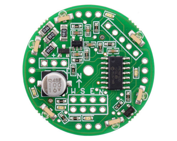
Pololu IR Beacon Development Board
The IR beacon development board is just an assembled IR Beacon PCB with no IR sensors or firmware. This item is intended for advanced users who want to customize their IR beacon functionality by writing their own firmware. No documentation is shipped with this IR Beacon Development kit.
| Description | Specs (6) | Pictures (3) | Resources (3) | FAQs (3) | On the blog (0) | Distributors (0) |
|---|
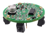 |
The Pololu IR beacons are small infrared transceivers meant to be used in pairs to give autonomous robots simple means for detecting each other. You can use the beacons to build pairs of robots that interact or chase one another, or to make a robot that can identify and return to a home base. For example, you could build a “cat robot” and “mouse robot” that each have an IR beacon, where the cat chases the mouse and the mouse runs away from the cat. The beacons are ideal for autonomous robot contests in which robots compete in pairs, such as MIT’s annual 6.270 autonomous robot design competition, where our original beacons were used for several years.
 |
These newer IR beacons feature round PCBs with six wide-angle emitters to provide uniform broadcasting in all directions. The operating voltage range has increased to 6 – 16 V, and on-board voltage monitoring enables a more consistent output brightness over the voltage range. Most components are pre-assembled, so all you need to solder is the connectors and sensors (make sure you solder them in from the bottom of the PCB!).
Note: The Pololu IR beacon is a kit; before using it, you need to assemble the beacon by soldering its components onto its circuit board. To use the kit in robotics projects, you need to connect it to your own robot controller. Please note that the IR beacons only work in pairs and that certain kinds of artificial lighting (e.g. some fluorescent lights) can interfere with the sensors.
Device Specifications
- PCB size: 1.35″ diameter
- IR modulation frequency: 56 kHz
- Output refresh rate 20 Hz
- Detection range: 6 inches to ~15 feet (typical; actual max range will depend on ambient lighting conditions)
- Supply voltage: 6-16 V
- Data voltage: 5 V
- Number of IR detectors: 4
How the IR Beacons Work
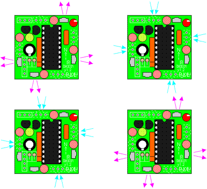
(The following animations show the old IR beacon, but the operating principle is the same in these newer, round units.)
The beacons work by transmitting and detecting infrared light, much like a television remote control. Each beacon has six IR emitters and four IR detectors. The beacons alternate between transmitting and receiving so that they never get confused by reflections of their own transmissions.
 |
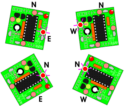
The transmit and detect cycle is carried out more than one thousand times per second, and a small microcontroller monitors all four detectors to decide the direction to the other beacon. The beacons have four red LEDs that indicate the direction to the other beacon; if you take two beacons and rotate them, the LEDs will always keep lighting up in the direction of the other beacon.
 |
Interfacing to the beacon is simple — it has four digital outputs that indicate which of its four sides detects the other beacon the strongest. You can establish the direction to another beacon to within a few degrees by rotating the beacon back and forth and noting the point where the output switches from one side to another. An enable input lets you select between active mode and a low-power mode.
IR Beacon Development Kit (Transmit-Only Beacon)
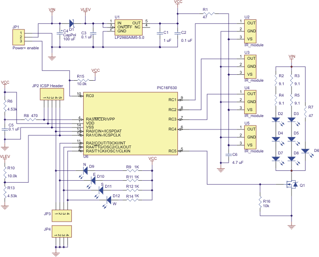
In response to customer requests, the IR beacon is available as just an assembled PCB with no IR sensors or firmware. This item is intended for advanced users who want to customize their IR beacon functionality by writing their own firmware. The main processor is a Microchip PIC16F630, and the PCB includes a footprint for a 5-pin header compatible with the PIC kit 2 programmer. The IR receiver modules are available separately. The schematic is shown below and is the only documentation shipped with this IR Beacon Development kit:
 |
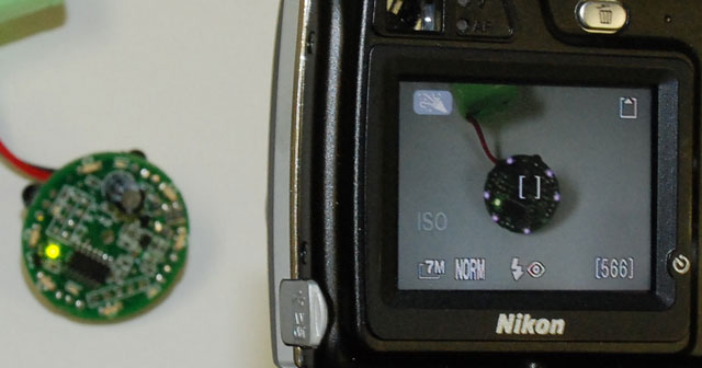
It is important to note that the IR beacon achieves its brightness by pulsing the IR LEDs with very high currents; turning on the IR LEDs continuously will burn them out. When testing the IR beacon, a digital camera can be useful in determining whether the IR LEDs are on. However, some cameras (usually more expensive ones) have better filters that block IR. In the picture below, a point-and-shoot camera shows the IR LEDs shining (in purple) but the DSLR with which the picture is taken does not show the LEDs.
 |
