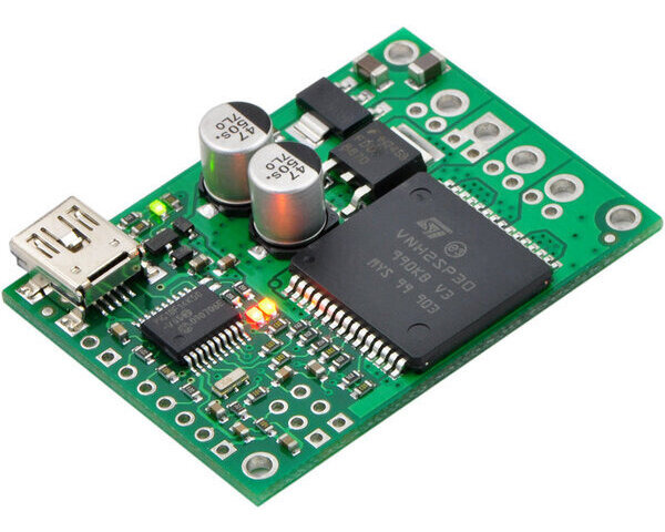
Jrk 12v12 USB Motor Controller with Feedback
The powerful Jrk 12v12 motor controller is a highly configurable brushed DC motor controller that supports four interface modes: USB, logic-level serial, analog voltage, and hobby radio control (RC). The controller can be used as an open-loop speed control or for closed-loop speed or position control. The continuous output current is approximately 12 A (30 A max) and the operating range of 6 V to 16 V (with transient protection up to 40 V).
Alternatives available with variations in these parameter(s): version Select variant…
| Description | Specs (15) | Pictures (16) | Resources (10) | FAQs (2) | On the blog (5) | Distributors (0) |
|---|
Overview
 |
The Jrk 12v12 is a versatile, general-purpose motor controller that supports a variety of interfaces, including USB. The 6 V to 16 V operating range and high continuous output current of 12 A (30 A peak) allow this board to control many medium-sized DC brushed motors. Analog voltage and tachometer (frequency) feedback options allow quick implementation of closed-loop servo systems, and a free configuration utility (for Windows) allows easy calibration and configuration through the USB port. A USB A to mini-B cable (not included) is required to connect this controller to a computer.
Key improvements over competing products and earlier Pololu motor controllers with feedback include:
- USB connectivity with emulated serial (COM) port allows direct motor control from a PC.
- Ultrasonic PWM to eliminate switching-induced motor shaft hum or whine.
- Robust, high-speed communication protocol with user-configurable error condition response.
- High internal resolution (12 bits) for smooth and flexible calibration to various input and feedback devices.
- Current sensing and limiting.
- Reversed power protection.
- Field-upgradeable firmware.
The table below lists the members of the Jrk family, including the original (green) and newer G2 (black) versions, and shows the key differences among them.
 Jrk 21v3 |
 Jrk G2 21v3 |
 Jrk G2 18v19 |
 Jrk G2 24v13 |
 Jrk G2 18v27 |
 Jrk G2 24v21 |
|
|---|---|---|---|---|---|---|
| Recommended max operating voltage: |
28 V(1) | 28 V(1) | 24 V(2) | 34 V(3) | 24 V(2) | 34 V(3) |
| Max nominal battery voltage: |
24 V | 24 V | 18 V | 28 V | 18 V | 28 V |
| Max continuous current (no additional cooling): |
2.5 A* | 2.6 A | 19 A | 13 A | 27 A | 21 A |
| USB, TTL serial, Analog, RC control: |
 |
 |
 |
 |
 |
 |
| I²C control: |  |
 |
 |
 |
 |
|
| Hardware current limiting: |  |
 |
 |
 |
||
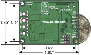
| Dimensions: | 1.35″ × 1.35″ | 1.0″ × 1.2″ | 1.4″ × 1.2″ | 1.7″ × 1.2″ | ||
| Price: | $74.95 | $54.95 | $109.95 | $109.95 | $149.95 | $149.95 |
| 1 Transient operation (< 500 ms) up to 40 V. 2 30 V absolute max. 3 40 V absolute max. * Reduced from “3 A” based on newer, more stringent tests. The value now is directly comparable to the rating for the newer G2 21v3. |
||||||
Main Features of the Jrk 12v12
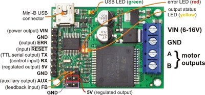 |
- Simple bidirectional control of one DC brush motor.
- 6 V to 16 V operating supply range.
- 12 A maximum continuous current output (30 A peak).
- Four communication or control options:
- USB interface for direct connection to a PC.
- Full-duplex, TTL-level asynchronous serial interface for direct connection to microcontrollers or other embedded controllers.
- Hobby radio control (RC) pulse width interface for direct connection to an RC receiver or RC servo controller.
- 0 V to 5 V analog voltage interface for direct connection to potentiometers and analog joysticks.
- Two closed-loop feedback options:
- 0 V to 5 V analog voltage.
- Frequency/tachometer digital input up to 2 MHz with 1 ms PID period.
- (Open-loop control with no feedback also available.)
 |
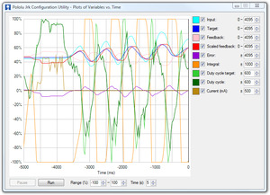 |
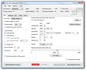
- Simple configuration and calibration over USB with free configuration program for Windows.
- Configurable parameters include:
- PID period and PID constants (feedback tuning parameters).
- Maximum current.
- Maximum duty cycle.
- Maximum acceleration.
- Error response.
- Input calibration (learning) for analog and RC control.
- Optional CRC error detection eliminates communication errors caused by noise or software faults.
- Reversed power protection.
- Field-upgradeable firmware.
- Optional feedback potentiometer disconnect detection.
- Comprehensive user’s guide.
Specifications
| Motor channels: | 1 |
|---|---|
| Operating voltage: | 6 V to 16 V |
| Continuous output current: | 12 A |
| Peak output current: | 30 A |
| Auto-detect baud rate range: | 300 bps to 115,200 bps |
| Available fixed baud rates: | 300 bps to 115,200 bps |
| Available PWM frequencies: | 20 kHz, 5 kHz |
| Reverse voltage protection?: | Yes |
| USB connector style: | USB Mini-B |
The Jrk 12v12 is the larger of two Jrk motor controllers. For a lower-power version that has a wider operating voltage range, see the Jrk 21v3.
Included Hardware
|
|
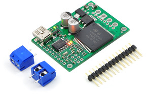
The Jrk ships with a straight 0.1″ breakaway male header strip and two 5mm, 2-pin terminal blocks. To provide maximum flexibility, none of these parts are soldered to the board.
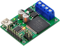
For the most compact installation, you can solder wires directly to the Jrk pads themselves and skip using the included hardware. The included hardware allows you to make less permanent connections. You can break the header strip into smaller pieces, such as an 8×1 piece and two 3×1 pieces, and solder these strips into the Jrk’s I/O pads.
The three mounting holes are intended for use with #2 screws (not included).
Firmware change notice: The latest firmware version for the Jrk 12v12, version 1.4, changes the way the motor is controlled when the duty cycle is set to 0. All Jrk 12v12s manufactured after August 24, 2012 ship with this new firmware version. You can tell what version of the firmware you have by running the Jrk Configuration Utility. See the Upgrading Firmware section of the user’s guide for more information.
People often buy this product together with:
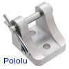 |
Mounting Bracket for Glideforce Light-Duty Linear Actuators - Aluminum |
